Cuff shaping device

A technology of setting device and chassis, applied in heating/cooling fabrics, textiles and papermaking, fabric surface trimming, etc., can solve the problem of easy movement of control pedals, and achieve the effect of avoiding damage to electrical components and preventing line damage

Inactive Publication Date: 2020-06-16
安徽豹子头服饰有限公司
View PDF11 Cites 0 Cited by
  • Summary
  • Abstract
  • Description
  • Claims
  • Application Information

AI Technical Summary

Problems solved by technology

[0004] The purpose of the present invention is to provide a cuff shaping device, which solves the problem that the control pedal of the existing cuff shaping device is easy to move, and performs anti-drag treatment on the pedal wires, optimizes the heat dissipation of the equipment control box, and prevents the airflow from directly Blowing into the control box will damage the electrical components, and the shock absorption design is adopted to reduce the vibration of the equipment

Method used


Image

  • Cuff shaping device
  • Cuff shaping device
  • Cuff shaping device

Examples


Embodiment

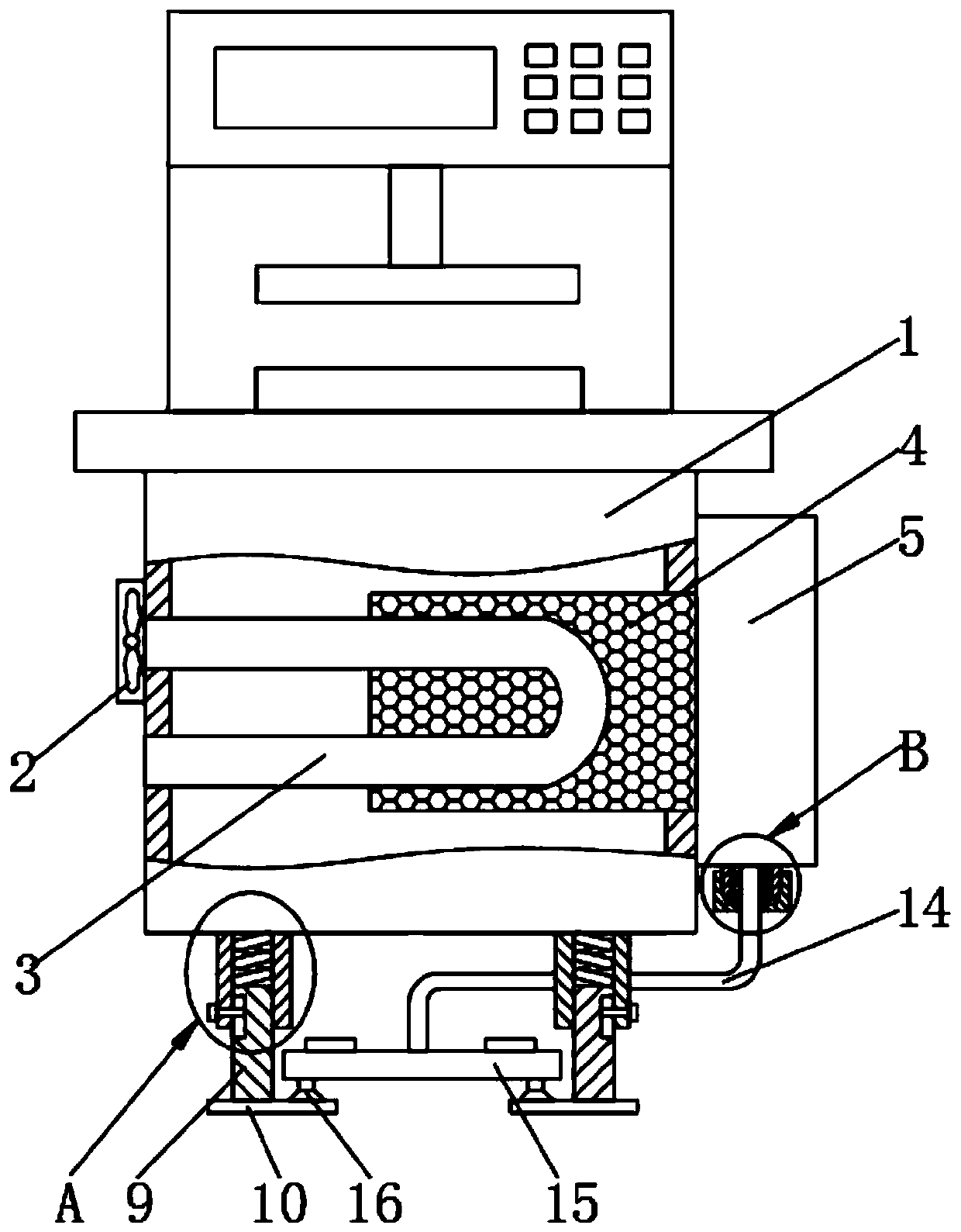
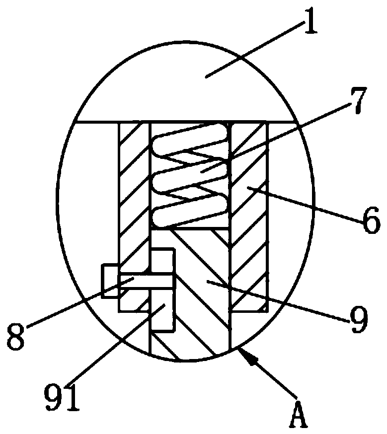
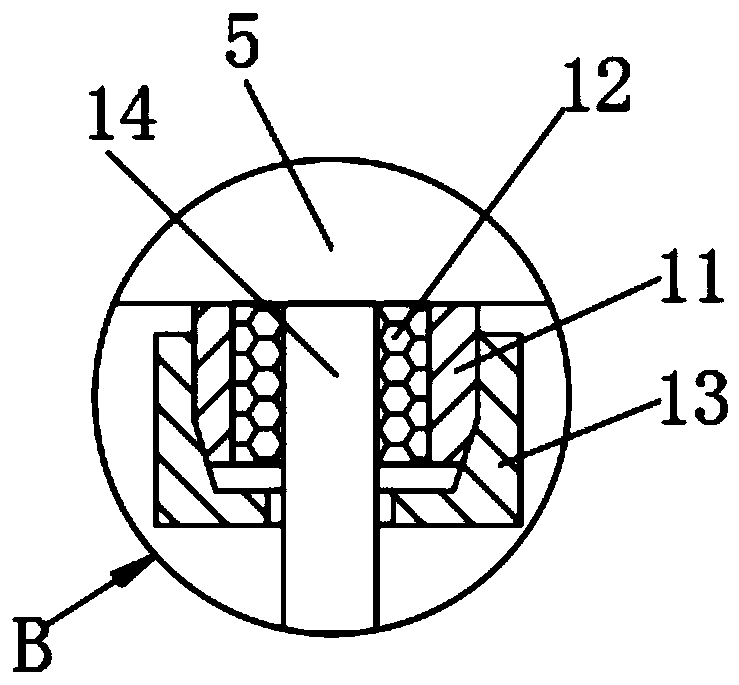
[0022] see Figure 1-5 , a cuff shaping device, comprising a case 1, a fan 2 is fixedly installed on the left end of the case 1, a heat dissipation pipe 3 is welded inside the case 1, a heat-conducting silica gel block 4 is attached to the outside of the heat dissipation pipe 3, and a right end of the case 1 is fixedly installed There is a control box 5, and various electrical components are installed in the control box 5, which belongs to the prior art. The lower end of the cabinet 1 is welded with a connecting sleeve 6, and a spring 7 is installed inside the connecting sleeve 6. The spring 7 has a shock-absorbing effect, and the connecting sleeve 6 The limit nail 8 is threaded inside, the guide column 9 is slidably connected to the connecting sleeve 6, the lower end of the guide column 9 is welded with a foot plate 10, the lower end of the control box 5 is welded with a threaded sleeve 11, and the control box 5 is led out with a wire 14. The outer side of 14 is fixedly conne...


PUM


Abstract

The invention belongs to the field of garment processing, and particularly relates to a cuff shaping device that comprises a chassis, wherein a fan is fixedly installed at the left end of the chassis,a radiating pipe is welded inside the chassis, a heat conductive silicone block is attached to the outside of the radiating pipe, a control box is fixedly installed at the right end of the chassis, aconnection sleeve is welded to the lower end of the chassis, a spring is installed inside the connection sleeve, a limit nail is connected into the connection sleeve by a thread, a guide post is connected in the connection sleeve by means of sliding, and a foot plate is welded to the lower end of the guide post. According to the invention, a suction cup is designed at the bottom of a control pedal, and the suction cup is sucked with the designed foot plate to prevent the control pedal from sliding randomly. A screw sleeve is designed at the bottom of a control box, a fastening sleeve is installed on the screw sleeve, and the lead of the control pedal is injection-connected to an injection sleeve, so that the injection sleeve is fixed by the fastening sleeve to prevent the lead from slipping, thereby protecting leads and preventing from faults caused by line damage during the transportation.

Description

technical field [0001] The invention relates to the technical field of garment processing, in particular to a cuff shaping device. Background technique [0002] The cuff refers to the edge of the lower mouth of the sleeve. In the cuff processing process, it is necessary to use a cuff setting machine to shape the cuffs. For example, use the existing air press cuff setting machine OP-606 to process the cuffs. [0003] However, the control pedal of the existing cuff setting machine is easy to slip, resulting in operation failure during the pedaling operation, and the wires of the control pedal lack anti-drag measures, and it is easy to pull during the handling process, which may lead to circuit failure inside the control box, and The control box lacks good heat dissipation measures, and the equipment also lacks shock absorption measures for protection. Therefore, it is necessary to improve the prior art. Contents of the invention [0004] The purpose of the present invent...

Claims


Application Information

Patent Timeline
IPC IPC(8): D06C7/02
CPCD06C7/02
Inventor 曹群李天全曹振李壮壮
Owner 安徽豹子头服饰有限公司
Why Eureka
Try Eureka