
Cross-over pipeline structure

A technology for bridging pipes and pipes, which is applied in the direction of pipes/pipe joints/fittings, pipes, rigid pipes, etc. It can solve the problems of increased thermal expansion displacement, restrictions, and high pressure of external transportation pipelines, so as to save engineering costs and avoid pipelines. The effect of damaging or improving economic benefits

Inactive Publication Date: 2014-04-09
CHINA NAT OFFSHORE OIL CORP +1
View PDF4 Cites 2 Cited by
  • Summary
  • Abstract
  • Description
  • Claims
  • Application Information

AI Technical Summary

Problems solved by technology

[0002] In offshore oil development projects, oil and gas resources are transported on the seabed through submarine oil pipelines. Since many oil and gas resources are located in deep water areas, and the inlet temperature of oil and gas resource pipelines is relatively high, the traditional structure design of expansion bends lying on the seabed is limited. limit
Then turn to the development mode of "submarine pipeline + underwater base plate", and the connection between the subsea pipeline and the base plate terminal used in this development mode is a key technical point, because the oil and gas resources extracted from the wellhead have a high temperature, The high pressure can easily cause the thermal expansion displacement of the outer pipeline to increase. Therefore, the general linear submarine pipeline cannot meet the requirements of production conditions, and a new type of submarine pipeline structure is required.

Method used


Image

  • Cross-over pipeline structure

Examples


Embodiment Construction

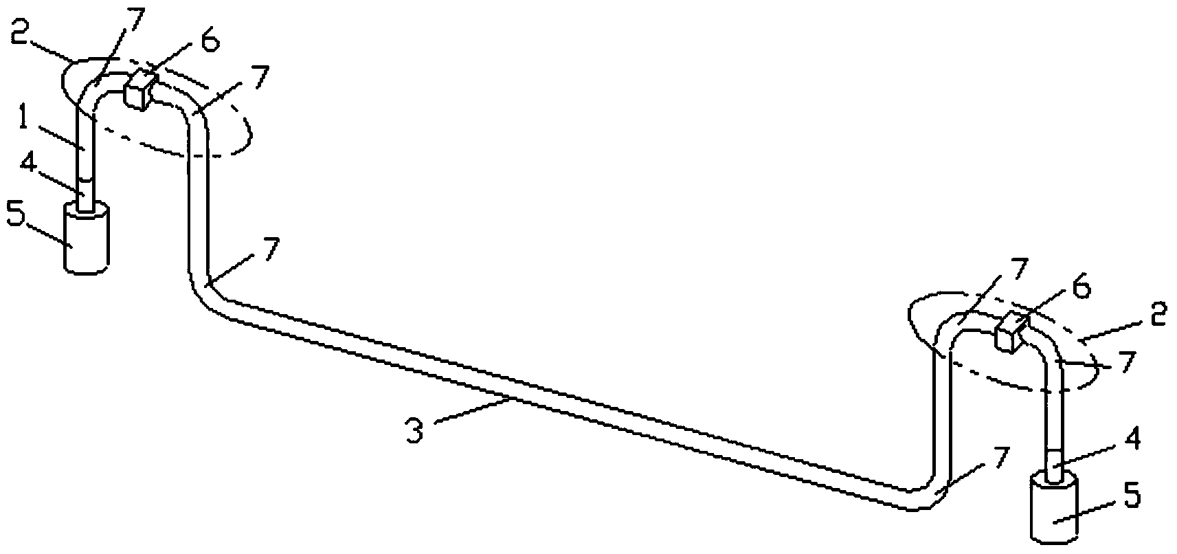
[0012] Such as figure 1 Shown, the present invention is provided with a pipeline 1, and this pipeline is The shape includes: a Π-shaped pipe section 2 arranged at both ends, an inverted Π-shaped pipe section 3 arranged in the middle, wherein the ends of the Π-shaped pipe section 2 at both ends are installed with a sleeve 4 for connecting with the submarine pipeline, A connector 5 for connecting the underwater pipeline to the wellhead or terminal is installed on the sleeve 4 , and the vertical part of the pipeline and the horizontal connection part are connected by an elbow 7 .

[0013] Above-mentioned pipeline 1 installs the operation panel 6 of ROV.

[0014] When in use, the present invention is lowered through the ship crane or winch installed on the sea, and installed on the underwater base plate and the wellhead or the pipeline terminal to connect the oil and gas resource transmission pipeline, and utilize the flexibility and structural strength of the structure itself t...


PUM


Abstract

A cross-over pipeline structure is provided with a pipeline shaped like a Chinese character 'ao'. The pipeline comprises inverted U-shaped pipe sections on the two end portions of the pipeline and a U-shaped pipe section in the middle of the pipeline. Sleeve pipes used for being connected with a subsea pipeline are arranged at the ends of the inverted U-shaped pipe sections on the two end portions of the pipeline, and connectors used for being connected with the subsea pipeline and a well mouth or a terminal are arranged on the sleeve pipes. Vertical parts and horizontal connecting parts are connected through bends. Through the characteristic of the structure of the cross-over pipeline structure, large flexibility strokes exist in the axial direction, thermal expansion displacement of the pipeline is effectively absorbed, the pipeline is prevented from being damaged by stress concentration and too large stress borne by the pipeline in the axial direction, and the safety production of an oil field is forcefully guaranteed. In addition, engineering cost is saved, and economic benefits are improved.

Description

technical field [0001] The invention relates to a pipeline structure, in particular to a bridging pipeline structure used for an underwater template of a submarine pipeline and a wellhead or a pipeline terminal, and belongs to the field of marine engineering. Background technique [0002] In offshore oil development projects, oil and gas resources are transported on the seabed through submarine oil pipelines. Since many oil and gas resources are located in deep water areas, and the inlet temperature of oil and gas resource pipelines is relatively high, the traditional structure design of expansion bends lying on the seabed is limited. limit. Then turn to the development mode of "submarine pipeline + underwater base plate", and the connection between the subsea pipeline and the base plate terminal used in this development mode is a key technical point, because the oil and gas resources extracted from the wellhead have a high temperature, The high pressure can easily cause th...

Claims


Application Information

Patent Timeline
IPC IPC(8): F16L9/22F16L51/00
CPCF16L9/22F16L51/00
Inventor 李志刚钟文军孙国民何宁杨琥郝双户赵党
Owner CHINA NAT OFFSHORE OIL CORP
Learn More