
Crankshaft damping wheel, mounting structure thereof, engine and vehicle

A technology of mounting structure and shock-absorbing wheel, applied in springs/shock absorbers, mechanical equipment, vibration suppression adjustment, etc., can solve problems such as increased engine friction, poor engine NVH, affecting driving experience, etc., and achieve engine friction reduction. Small, lower fuel consumption, better driving experience

Pending Publication Date: 2020-06-16
GUANGZHOU AUTOMOBILE GROUP CO LTD
View PDF0 Cites 1 Cited by
  • Summary
  • Abstract
  • Description
  • Claims
  • Application Information

AI Technical Summary

Problems solved by technology

[0002] The existing technical solution crankshaft damping pulley (crankshaft damping pulley) is arranged outside the front cover of the engine, and the crankshaft passes through the front cover of the engine and is sealed by an oil seal. Due to the existence of the oil seal, the friction of the engine will inevitably increase, and the fuel consumption of the whole vehicle is about Increase 0.5g / Kwh, and there is a certain risk of oil leakage; moreover, the internal noise of the engine is transmitted to the outside through the small head of the crankshaft, the front cover plate, and the damping wheel of the crankshaft, resulting in poor engine NVH (English abbreviation for Noise, Vibration, Harshness), Affect the driving experience

Method used


Image

  • Crankshaft damping wheel, mounting structure thereof, engine and vehicle
  • Crankshaft damping wheel, mounting structure thereof, engine and vehicle
  • Crankshaft damping wheel, mounting structure thereof, engine and vehicle

Examples


Embodiment Construction

[0021] In order to make the object, technical solution and advantages of the present invention clearer, the present invention will be further described in detail below in conjunction with the accompanying drawings and embodiments. It should be understood that the specific embodiments described here are only used to explain the present invention, not to limit the present invention.

[0022] It should be noted that the terms "setting" and "connecting" should be understood in a broad sense, for example, they can be directly set and connected, or indirectly set and connected through a central component or a central structure.

[0023] In addition, if there are "longitudinal", "transverse", "length", "width", "thickness", "upper", "lower", "front", "rear", "left", " Terms such as "right", "vertical", "horizontal", "top", "bottom", "inner", "outer", etc. indicate the orientation or positional relationship, which are based on the orientation or positional relationship shown in the dr...


PUM


Abstract

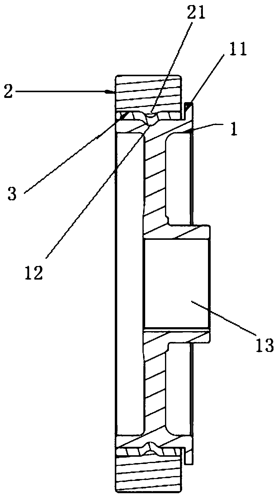
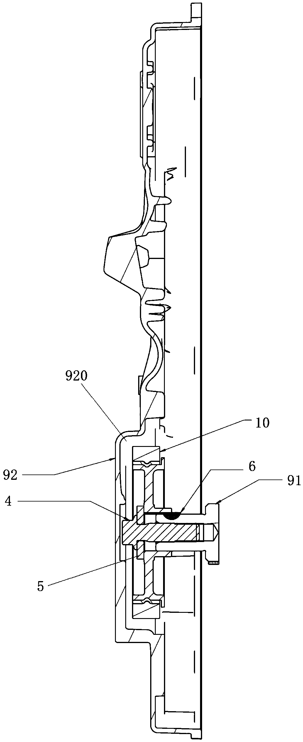
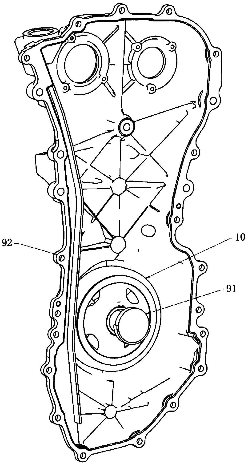
The invention is applicable to the technical field of engines and vehicles, and discloses a crankshaft damping wheel, a mounting structure thereof, an engine and a vehicle. The crankshaft damping wheel comprises a wheel body located in an engine front cover plate, the wheel body comprises a hub connected with a crankshaft, an inertia ring mounted on the hub in a sleeving manner and a rubber ring mounted between the Inertia ring and the hub, the mounting structure is provided with the crankshaft damping wheel, the engine is provided with the mounting structure, the vehicle is provided with theengine, according to the crankshaft damping wheel, the mounting structure thereof, the engine and the vehicle, the crankshaft damping wheel is mounted in the engine, a crankshaft does not need to penetrate through the engine front cover plate, a penetrating hole and an oil seal do not need to be mounted on the engine front cover plate, the rotating resistance of the crankshaft is small, the friction of the engine is relatively reduced, the whole vehicle oil consumption is reduced, the way of transmitting the engine noise to the outside can be reduced, NVH of the engine can be improved, and theuser driving and taking experience is better.

Description

technical field [0001] The invention belongs to the technical fields of engines and vehicles, and in particular relates to a crankshaft damping wheel and its installation structure, an engine and a vehicle. Background technique [0002] The existing technical solution crankshaft damping pulley (crankshaft damping pulley) is arranged outside the front cover of the engine, and the crankshaft passes through the front cover of the engine and is sealed by an oil seal. Due to the existence of the oil seal, the friction of the engine will inevitably increase, and the fuel consumption of the whole vehicle is about Increase 0.5g / Kwh, and there is a certain risk of oil leakage; moreover, the internal noise of the engine is transmitted to the outside through the small head of the crankshaft, the front cover plate, and the damping wheel of the crankshaft, resulting in poor engine NVH (English abbreviation for Noise, Vibration, Harshness), affect the driving experience. Contents of the...

Claims


Application Information

Patent Timeline
Patent Type & Authority Applications(China)
IPC IPC(8): F16F15/126F16F15/26
CPCF16F15/126F16F15/26F16F2230/0029
Inventor 易敬华杨江吴广权占文锋黄宇
Owner GUANGZHOU AUTOMOBILE GROUP CO LTD
Learn More