Damper bearing

A technology of damping bearings and damping rings, which is applied in the field of damping bearings, can solve the problems of abnormal wear of moving rings and damping rings, reduce the service life of bearings, and easy entry of impurities, so as to achieve smooth operation, reduced rotational resistance and long service life. Effect

Active Publication Date: 2014-10-08
CHONGQING CHUANGHONG ELECTROMECHANICAL
View PDF9 Cites 12 Cited by
  • Summary
  • Abstract
  • Description
  • Claims
  • Application Information

AI Technical Summary

Problems solved by technology

Planar damping bearings are widely used in steering knuckles of automobiles. The fixed ring is closely matched with the casing, and the moving ring is used for rotation. The poor sealing performance of the existing planar damping bearings makes it easy for impurities to enter the damping ring, causing abnormalities between the moving ring and the damping ring. wear, reducing bearing life

Method used


Image

  • Damper bearing
  • Damper bearing
  • Damper bearing

Examples


Embodiment 1

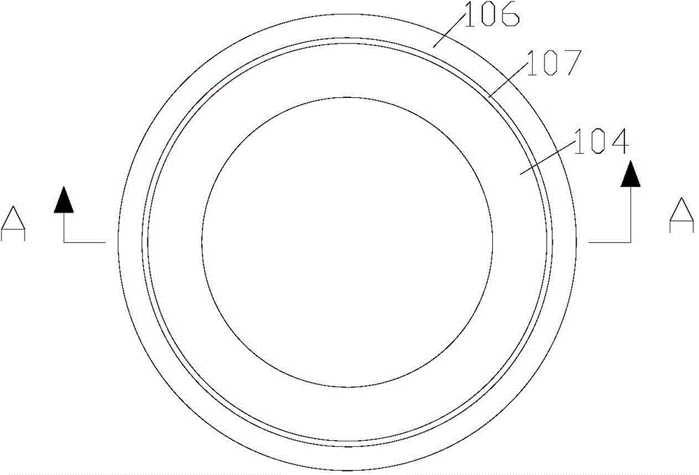
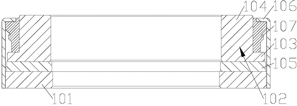
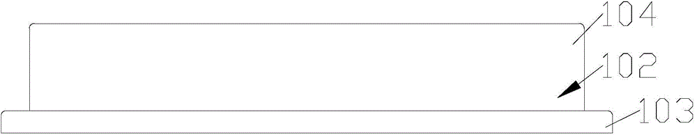
[0036] Figure 1-Figure 17 It shows the damping bearing provided by Embodiment 1 of the present invention, including: fixed ring 101; The moving ring 104 is integrally formed, the first moving ring 103 is closer to the fixed ring 101 than the second moving ring 104, the outer diameter of the first moving ring 103 is larger than the outer diameter of the second moving ring 104; the damping ring 105, the damping ring 105 is set Between the first moving ring 103 and the fixed ring 101; the casing 106, the fixed ring 101, the moving ring 102 and the damping ring 105 are all arranged inside the casing 106, the casing 106 is fixed to the fixed ring 101, and the casing 106 is far away from the fixed ring 101 The inner diameter of one end is less than the outer diameter of the first moving ring 103, and the second moving ring 104 passes through the casing 106; the sealing ring 107, the sealing ring 107 is arranged on the outer diameter of the casing 106, the first moving ring 103 and ...

Embodiment 2

[0039] Figure 18-Figure 25 It shows the damping bearing provided by Embodiment 2 of the present invention. Compared with Embodiment 1, the improvement of this embodiment is that four drag-reducing oil grooves 108 are arranged on the damping ring 105, and the drag-reducing oil grooves 108 are arranged on the damping ring 105 The side close to the first moving ring 103. The side of the damping ring 105 close to the first moving ring 103 is provided with a drag reducing oil groove 108, and a special grease can be injected into the drag reducing oil groove 108, so that the first moving ring 103 and the damping ring 105 can be lubricated to reduce the rotational resistance In addition, the drag reducing oil groove 108 reduces the contact area between the damping ring 105 and the first moving ring 103, which can also reduce the rotational resistance, and the damping bearing runs more smoothly.

[0040] Further, the thickness of the damping ring 105 is 4cm. The damping ring 105 is...


PUM


Abstract

The invention provides a damper bearing, belonging to the field of bearing. The damper bearing comprises a fixed loop, a movable loop, a damping loop, a shell and a sealing ring, wherein the movable loop comprises a first movable loop and a second movable loop which are connected with each other, the first movable loop is closer to the fixed loop relative to the second movable loop, the outer diameter of the first movable loop is greater than the outer diameter of the second movable loop; the damping loop is arranged between the first movable loop and the fixed loop; the fixed loop, the movable loops and the damping loop are arranged in the shell, and the shell is fixed with the fixed loop, the inner diameter of one end of the shell, far away from the fixed loop, is smaller than the outer diameter of the first movable loop, and the second movable loop penetrates through the shell; the sealing ring is arranged in a region formed by surrounding of the shell, the first movable loop and the second movable loop. The damper bearing with the structure can alleviate the abnormal abrasion between the damping loop and the first movable loop caused by impurities so that the service life of the damper bearing is long, and the performance is stable.

Description

technical field [0001] The invention relates to the field of bearings, in particular to damping bearings. Background technique [0002] Damping bearings are a kind of bearings. Generally, one-way damping bearings are used. There is no resistance when rotating in the forward direction, and the resistance is relatively large or cannot rotate in the reverse direction. It is mainly used to reduce the rotation of the shaft and improve the stability of the rotor system. sex. Planar damping bearings are widely used in steering knuckles of automobiles. The fixed ring is closely matched with the casing, and the moving ring is used for rotation. The poor sealing performance of the existing planar damping bearings makes it easy for impurities to enter the damping ring, causing abnormalities between the moving ring and the damping ring. Wear and reduce the service life of the bearing. Contents of the invention [0003] The present invention provides a damping bearing to solve the ab...

Claims


Application Information

Patent Timeline
Patent Type & Authority Applications(China)
IPC IPC(8): F16C17/08
Inventor 赵鸿荣付果元
Owner CHONGQING CHUANGHONG ELECTROMECHANICAL
Why Eureka
Try Eureka