Electrostatic gun with integrated gun head

An electrostatic gun, an integrated technology, applied in the field of electrostatic guns, can solve the problems of slow switching of discharge gun heads, reduced test efficiency, short service life, etc.

Pending Publication Date: 2020-06-16
广东省医疗器械质量监督检验所
0 Cites 0 Cited by

AI-Extracted Technical Summary

Problems solved by technology

[0003] The present invention aims to overcome the defects of slow switching of discharge gun heads in the prior art, reduced test efficiency, inconvenient operation, and short service life, an...

Abstract

The invention relates to the field of electromagnetic compatibility testing, and provides an electrostatic gun with an integrated gun head. The electrostatic gun comprises an outer shell, a control circuit, an output gun head, two discharge gun heads and a switching mechanism, wherein the control circuit is arranged in the outer shell, one end of the output gun head is inserted into the outer shell, connected to the front end of the electrostatic gun and electrically connected with the control circuit; the other end of the output gun head is inserted into the switching mechanism, and the two discharge gun heads are inserted into the switching mechanism; and through rotating the switching mechanism, the output gun head is electrically contacted with the two discharge gun heads respectively.Through arranging the two discharge gun heads on the same electrostatic gun, and switching the discharge gun heads through the switching mechanism, the purposes of improving the test efficiency, being convenient to operate and prolonging the service life can be achieved; through the optimization design of the switching structure, the purposes of convenient operation and cost saving are achieved;and the outer shell, the control circuit, the display panel, the battery and the like are arranged, so that the operation of a user is facilitated.

Application Domain

Electrical measurement instrument detailsMeasuring interference from external sources

Technology Topic

Electromagnetic compatibilityElectrical battery +4

Image

  • Electrostatic gun with integrated gun head
  • Electrostatic gun with integrated gun head
  • Electrostatic gun with integrated gun head

Examples

  • Experimental program(1)

Example Embodiment

[0024] Example 1
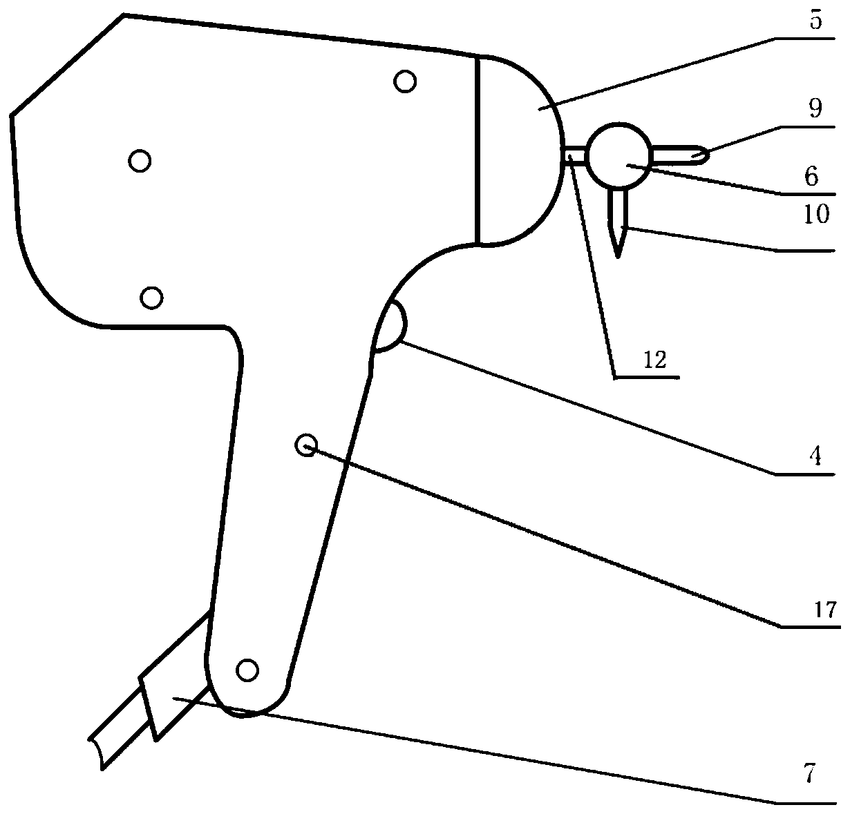
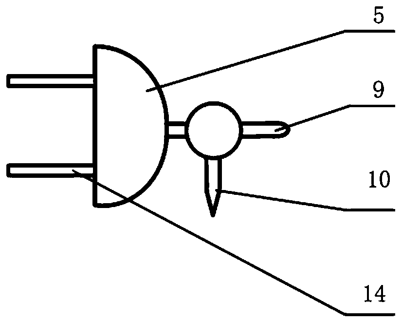
[0025] This embodiment provides an electrostatic gun with an integrated gun head, which includes a housing, a control circuit, an output gun head 12, two discharge gun heads, and a switching mechanism 6. The control circuit is arranged in the housing.
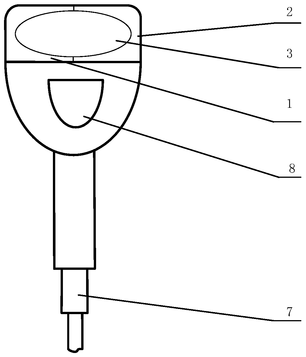
[0026] Such as figure 1 with figure 2 As shown, the housing includes a left cover 1, a right cover 2, and a gun head base 5. The left cover 1 and the right cover 2 have the same shape and are generally in a "T" shape. The left cover 1 and the right cover 2 are symmetrically distributed in the electrostatic The outer sides of the gun are buckled together, and the left cover 1 and the right cover 2 can be locked to the electrostatic gun by fasteners 17 respectively. The left cover 1 and the right cover 2 can be locked by five fasteners 17 respectively, and the left cover 1 and the right cover 2 are respectively provided with holes corresponding to the fasteners 17. The gun head base 5 has a hemispherical shape and can be detachably connected to the left cover 1 and the right cover 2, and is located at the front end of the electrostatic gun.
[0027] The electrostatic gun also includes a battery, a display panel 3, and a discharge button 4 all connected to the control circuit. The battery is provided with a battery cover 8 which is provided on the housing. The display panel 3 has an oval shape and is located between the left cover 1 and the right cover 2; both the left cover 1 and the right cover 2 are provided with openings, and the through holes formed by the openings of the left cover 1 and the openings of the right cover 2 and the display panel The outline of 3 fits. The display panel 3 displays the level of electrostatic discharge, such as +2KV, +4KV, +6KV, etc. The display panel 3 is also located at the rear end of the electrostatic gun, and the battery cover 8 is located below the display panel 3. The discharge button 4 is located at the front end of the electrostatic gun, and the discharge button 4 can be used to control the discharge switch of the electrostatic gun.
[0028] The lower end of the electrostatic gun is also provided with a cable 7, and the lower end of the casing is provided with a lead hole, the cable 7 is connected to the control circuit through the lead hole, and the cable 7 is connected with an external power source, and has a complementary relationship with the battery. The battery can be a rechargeable battery or a storage battery. When the external power supply is suddenly disconnected, the battery can continue to supply power to the electrostatic gun to avoid sudden interruption of the electrostatic gun during the test.
[0029] Such as image 3 As shown, the rear end of the gun head base 5 is provided with metal pins 14, the left cover 1 and the right cover 2 are both provided with guide holes, and the metal pins 14 are connected to the control circuit through the guide holes.
[0030] Such as Figure 4 with Figure 5 As shown, the discharge gun tip may include an air discharge gun tip 9 and a contact discharge gun tip 10, but is not limited to the air discharge gun tip 9 and the contact discharge gun tip 10. The air discharge gun head 9 and the contact discharge gun head 10 are arranged in the switching mechanism 6 perpendicular to each other.
[0031] The switching mechanism 6 is provided with a cavity 15 inside. The cross section of the cavity 15 can be rectangular, circular, preferably rectangular. In this way, the air discharge gun head 9 and the contact discharge gun head 10 are respectively arranged on the short sides of the rectangle and On the long side, it can be determined that the air discharge gun head 9 and the contact discharge gun head 10 are perpendicular to each other.
[0032] The switching mechanism 6 is spherical, and the cavity 15 is eccentrically arranged in the spherical body. The output gun head 12, the air discharge gun head 9 and the contact discharge gun head 10 are all inserted into the cavity 15 of the switching mechanism 6. The length of the output gun head 12 and the air discharge gun head 9 and the contact discharge gun head 10 inserted into the cavity 15 is different, and the length of the air discharge gun head 9 is greater than the length of the contact discharge gun head 10. The switching mechanism 6 is further provided with a groove 16 which communicates with the cavity 15. The inner wall of the groove 16 is provided with a plurality of locking slots 11, and the locking slots 11 correspond to the air discharge gun head 9 and the contact discharge gun head 10 one by one and are on the same straight line. The locking slot 11 fits with the output gun head 12, and a bump that can be matched with the locking slot 11 can be provided on the output gun head 12.
[0033] One end of the output gun head 12 is inserted into the gun head base 5 to be connected to the front end of the electrostatic gun, and can be electrically connected to the control circuit through the metal pin 14, and the other end is inserted into the switching mechanism 6. The front end of the output gun head 12 is provided with a spring top block 13, the output gun head 12 is connected to the spring top block 13 through a spring, and the output gun head 12 contacts the discharge gun head through the spring top block 13. The upper end surface of the spring top block 13 is a curved surface, and the air discharge gun head 9 and the mating surfaces of the contact discharge gun head 10 and the spring top block 13 are also set to be curved surfaces, which facilitates switching between different gun heads.
[0034] During the operation, turn the switching mechanism 6, the output gun head 12 is stuck in the slot 11 and is in electrical contact with the air discharge gun head 9 or the contact discharge gun head 10, adjust the test level through the display panel, and press the discharge button 4 to treat Test the product for testing.

PUM

no PUM

Description & Claims & Application Information

We can also present the details of the Description, Claims and Application information to help users get a comprehensive understanding of the technical details of the patent, such as background art, summary of invention, brief description of drawings, description of embodiments, and other original content. On the other hand, users can also determine the specific scope of protection of the technology through the list of claims; as well as understand the changes in the life cycle of the technology with the presentation of the patent timeline. Login to view more.

Similar technology patents

Vulnerability scanning method, device and electronic device

ActiveCN105516131Ashorten the timeImprove vulnerability scanning efficiency
Owner:ZHUHAI BAOQU TECH CO LTD

Classification and recommendation of technical efficacy words

  • shorten the time
  • Improve operational efficiency

Alarm association rule obtaining method of mobile internet

ActiveCN102098175AAccurate resultsImprove operational efficiency
Owner:INSPUR TIANYUAN COMM INFORMATION SYST CO LTD

Automatic robot, control device and control method

Owner:BEIJING XIAOMI MOBILE SOFTWARE CO LTD +1

Operation processing method and device

Owner:BUBI BEIJING NETWORK TECH CO LTD

Automatic guided vehicle (AGV) scheduling control system

InactiveCN109669456AImprove operating system efficiencyImprove operational efficiency
Owner:WUHU HIT ROBOT TECH RES INST
Why Eureka
Try Eureka