
Combined motor structure and control method thereof

A motor structure and combined technology, applied in the mechanical field, can solve the problems of unstable rotation speed, inability to precisely control the stop position, and eccentric rotation of the output rod.

Pending Publication Date: 2020-06-16
南通杰玛电机有限公司
View PDF0 Cites 0 Cited by
  • Summary
  • Abstract
  • Description
  • Claims
  • Application Information

AI Technical Summary

Problems solved by technology

[0002] The motor is a commonly used power device, but the existing motors have the following problems: 1. When the motor is connected to a carrier, if the weight of the carrier is too large, it is easy to be eccentric, resulting in the eccentric rotation of the output rod; 2. When the existing motor stops, use The most important thing is the frictional stop, which will take a long time to stop the rotation after the power supply is stopped, resulting in the inability to accurately control the stop position
3. The rotor of a motor is greatly affected by the current, and the current is likely to cause the instability of the speed

Method used


Image

  • Combined motor structure and control method thereof
  • Combined motor structure and control method thereof

Examples


Embodiment

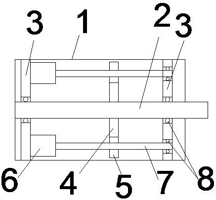
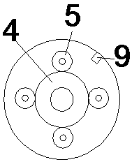
[0018] Such as figure 1 A combined motor structure is shown, including a housing 1, the main output shaft 2 is connected to the inner axis of the housing 1, and the fixed plate 3 is fixed at both ends of the housing 1; the main output shaft 2 is axially connected to the fixed plate 3; The transmission gear 4 is fixed on the output shaft 2, and the transmission gear 4 is meshed with several groups of driving gears 5 arranged symmetrically; the driving gears 5 are respectively connected with a rotating device 6; Connected and axially connected to the fixed plate 3; when the rotating device 6 drives the main output shaft 2 to rotate and output through the driving gear 5 and the transmission gear 4, the driving current of at least one rotating device 6 is smaller than that of the remaining rotating devices 6.

[0019] The rotating device 6 is a motor. A gear speed sensor 9 for detecting the speed of the transmission gear 4 is installed on the housing 1 .

[0020] Both the main o...


PUM


Abstract

The invention relates to a combined motor structure, which comprises a housing. A main output shaft is coupled in the housing, and fixing plates are fixed at two ends of the housing; the main output shaft is coupled to the fixing plates; a transmission gear is fixed on the main output shaft, and is meshed with a plurality of groups of driving gears which are symmetrically arranged; the driving gears are respectively connected with a rotating device; and output shafts of the rotating devices are fixedly connected with the driving gears and coupled to the fixing plates. According to the invention, screening and speed limiting of current fluctuation are realized by reducing the driving current of one motor, so that unstable rotating speed caused by current fluctuation in the running process of the motor is reduced; rapid stalling of the main output shaft is achieved through reverse rotation of the motor, so that stalling position control is more accurate; and rapid locking of the main output shaft is achieved through forward and reverse relative rotation relative to the motor, then the motor stops rotating, the stability of the main output shaft is kept through a friction stalling device in the motor, and rapid locking of the main output shaft is achieved.

Description

technical field [0001] The invention belongs to the field of machinery, and in particular relates to a combined motor structure and a control method thereof. Background technique [0002] The motor is a commonly used power device, but the existing motors have the following problems: 1. When the motor is connected to a carrier, if the weight of the carrier is too large, it is easy to be eccentric, resulting in the eccentric rotation of the output rod; 2. When the existing motor stops, use The most important thing is the frictional stop, which will take a long time to stop the rotation after the power supply is stopped, resulting in the inability to accurately control the stop position. 3. The rotor of a motor is greatly affected by the current, and the current is likely to cause the instability of the speed. Contents of the invention [0003] In order to solve the above problems, the present invention discloses a combined motor structure and its control method. The present...

Claims


Application Information

Patent Timeline
Patent Type & Authority Applications(China)
IPC IPC(8): H02K7/10H02K7/116H02K7/20
CPCH02K7/10H02K7/116H02K7/20
Inventor 冯汝生
Owner 南通杰玛电机有限公司
Learn More