
Link time delay detection method and device, equipment and medium

A detection method and delay technology, applied in the field of communication, can solve problems such as limiting practical applications, link quality not being measured and monitored, etc.

Active Publication Date: 2020-06-16
LIAONING MOBILE COMM +1
View PDF4 Cites 6 Cited by
  • Summary
  • Abstract
  • Description
  • Claims
  • Application Information

AI Technical Summary

Problems solved by technology

The quality of other member links is not measured and monitored
[0011] In addition, a small number of equipment manufacturers increase the aggregation member information field in the reserved bytes of the TWAMP control message, and negotiate the sending port and reflection port of the devices at both ends through the control message before sending the test message. Independent testing of member links, but the definition and use of this reserved byte is currently stipulated in the non-Request For Comments (RFC) standard, which belongs to the customization of a small number of equipment manufacturers
There is a problem of intercommunication between devices from different manufacturers, which limits the practical application in the network

Method used


Image

  • Link time delay detection method and device, equipment and medium
  • Link time delay detection method and device, equipment and medium
  • Link time delay detection method and device, equipment and medium

Examples


Embodiment Construction

[0058] The characteristics and exemplary embodiments of various aspects of the present invention will be described in detail below. In order to make the purpose, technical solutions and advantages of the present invention more clear, the present invention will be further described in detail below in conjunction with the accompanying drawings and embodiments. It should be understood that the specific embodiments described here are only configured to explain the present invention, not to limit the present invention. It will be apparent to one skilled in the art that the present invention may be practiced without some of these specific details. The following description of the embodiments is only to provide a better understanding of the present invention by showing examples of the present invention.

[0059] It should be noted that in this article, relational terms such as first and second are only used to distinguish one entity or operation from another entity or operation, and ...


PUM


Abstract

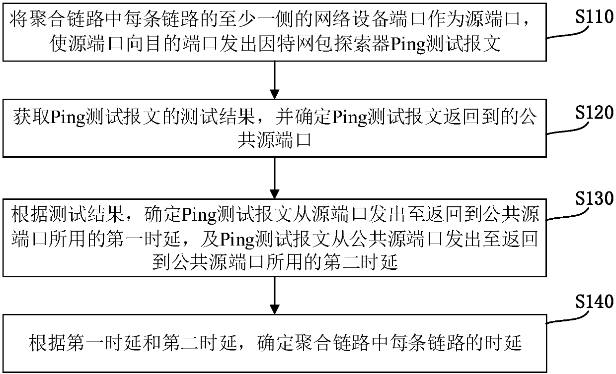
The invention discloses a link time delay detection method and device, equipment and a medium. The method comprises the following steps: taking a network equipment port on at least one side of each link in an aggregation link as a source port, and enabling the source port to send an Internet packet explorer Ping test message to a destination port; obtaining a test result of the Ping test message,and determining a common source port to which the Ping test message returns; according to the test result, determining a first time delay from sending of the Ping test message from the source port toreturning to the public source port and a second time delay from sending of the Ping test message from the public source port to returning to the public source port; and determining the time delay ofeach link in the aggregated link according to the first time delay and the second time delay. According to the embodiment of the invention, the time delay of each link in the aggregated link can be detected.

Description

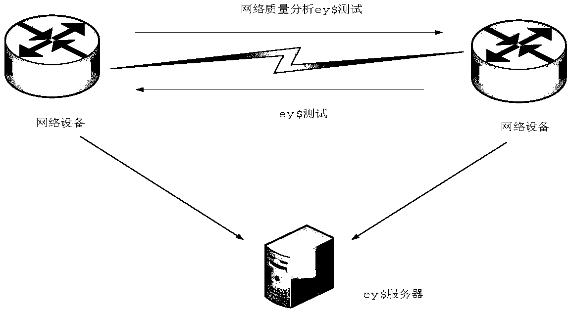
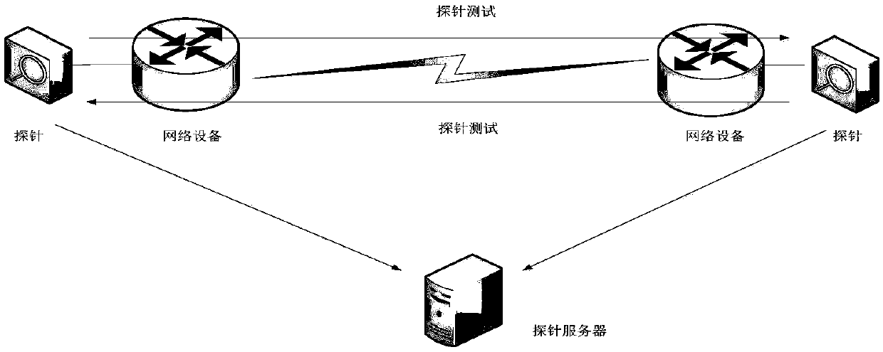
technical field [0001] The present invention relates to the field of communication technology, in particular to a detection method, device, equipment and medium of link time delay. Background technique [0002] At present, communication operators generally adopt a multi-port physical link aggregation mode in an Internet Protocol (IP) network interconnected between networks, and interconnect devices using aggregated links. Latency is one of the important indicators reflecting the network quality between two network devices, which directly affects the service signal quality flowing between the devices and ultimately affects the user's service perception. [0003] To detect the time delay between network devices, it usually deploys test tasks between network devices, and obtains the network quality index of time delay by recording the test tasks. Usually there are two situations: [0004] The first case: if figure 1 As shown, a Network Quality Analyzer (NQA) test is deployed...

Claims


Application Information

Patent Timeline
IPC IPC(8): H04L12/26
CPCH04L43/087H04L43/10
Inventor 郑松
Owner LIAONING MOBILE COMM
Learn More