Method and system of fault detection and localisation in DC-systems

a fault detection and fault technology, applied in photovoltaic monitoring, instruments, measurement devices, etc., can solve the problems of easy complexity of fault finding, assumed faults, and difficult fault localisation, and achieve reliable detection of faulty bpds

Active Publication Date: 2017-07-27
EMAZYS APS
View PDF2 Cites 10 Cited by
  • Summary
  • Abstract
  • Description
  • Claims
  • Application Information

AI Technical Summary

Benefits of technology

[0038]It is therefore advantageous to ascertain whether the DC current drawn by the weak load is large enough to ensure that the voltage across any shaded string of cells is large enough to turn on its associated BPD. This can be done by measuring the unloaded impedance of the PV string under daylight conditions and with a known number of PV cells in a PV panel fully shaded. Here, it is also of importance to note that there can be large variations from cell to cell in systems that have been subject to ageing over several years. Here, it is often seen that the semi-conducting barriers in some cells can be entirely destroyed basically acting as shorts regardless of the illumination intensity. When estimating the impedance of shaded cells it is therefore advantageous to shade a significant number of cells (say 20-50 cells or more in say a 100-1000 cell system), so that the resulting measured impedance per cell is representative of the average cell impedance in the entire string of modules.
[0039]Thus, having a load or a weak load in the sense of a load sufficient to fully turn on a by-pass diode has been found to enable reliable detection of faulty BPDs.

Problems solved by technology

However, DC systems may in reality become complex systems when assembled and during operation.
The task of fault finding easily becomes complex and assumed faults and their localisation in a system may when the actual component is found and inspected turn out not to be faulty or located where expected.
Likewise fault localisation may be very time consuming if not practically unfeasible or even impossible if each source is to be tested individually.
In particular, DC-systems may during installation be installed with deviations from the intended installation and faults may be introduced.
Likewise a DC-system may become damaged or degenerate over time with a huge number of combinations of possible faults.
However, the fault localisation procedure requires use of additional setup including a DC BIAS.
Also the method requires analysis of the measurement in a different domain (time domain reflectometry), which adds complexity to the procedure.
Prior art including the patent application WO2012152284 is also limited in a further aspect by suggesting use of systems or methods that need to be individually configured or applied.
Thus, although individual faults may be detected and localized, different apparatuses or methods must be connected, disconnected or reconfigured to accomplish measurements.

Method used


Image

  • Method and system of fault detection and localisation in DC-systems
  • Method and system of fault detection and localisation in DC-systems
  • Method and system of fault detection and localisation in DC-systems

Examples


Embodiment Construction

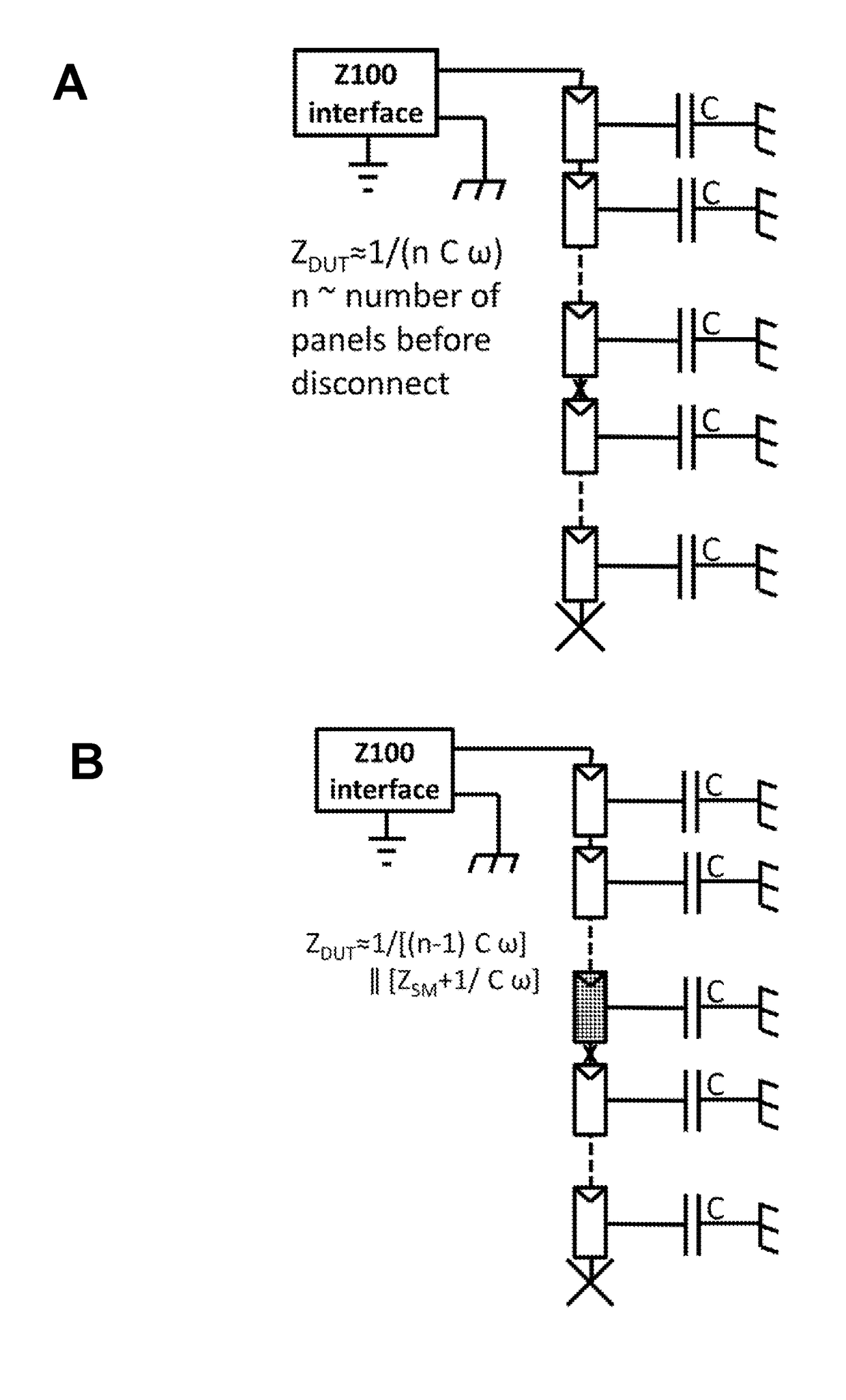
[0012]An objective of the invention is achieved by a method of fault detection and localisation of a fault in a DC-system comprising multiple serially connected DC-sources.

[0013]The method may comprise an act of connecting a test apparatus to at least one terminal of the DC-system and to DC-system ground.

[0014]The method encompasses at least one repetition of an act of applying a test AC-signal to the least one terminal of the DC-system, an act of detecting the response AC-signal to the test AC-signal on either one terminal alone and / or on DC-system ground; and an act of comparing the response AC signal with the test AC-signal to detect a fault and the location of the fault in the DC-system.

[0015]Thereby, a robust procedure and reliable procedure is disclosed.

[0016]If there are no ground faults, a prior art LCR meter could be safely connected to the anode or cathode and ground terminals. However such assumption or elimination of ground faults will complicate and disturb the fault de...


PUM


Abstract

This disclosure relates to a method of and a system for fault detection and localisation of a fault in a DC-system comprising multiple serially connected DC-sources. The method may comprise an act of connecting a test apparatus to at least one terminal of the DC-system and to DC-system ground. The method encompasses at least one repetition of an act of applying a test AC-signal to one terminal of the DC-system, an act of detecting the response AC-signal to the test AC-signal on either one terminal alone and/or on DC-system ground; and an act of comparing the test AC signal with the response AC-signal to detect a fault and the location of the fault in the DC-system. The system comprises a fault detection and localisation apparatus configured to perform the method disclosed.

Description

FIELD OF THE INVENTION[0001]The present invention relates to a method of and a system for fault detection and localisation of a fault in a DC-system comprising multiple serially connected DC-sources.[0002]The method may comprise an act of connecting a test apparatus to at least one terminal of the DC-system and to DC-system ground (GND). The method encompasses at least one repetition of an act of applying a test AC-signal to the least one terminal of the DC-system, an act of detecting the response AC-signal to the test AC-signal on either one terminal alone and / or on DC-system GND; and an act of comparing the response AC signal with the test AC-signal to detect a fault and the location of the fault in the DC-system.[0003]The system may comprise a fault detection and localisation apparatus configured for detection and localisation of a fault in a DC-system comprising multiple serially connected DC-sources. Such fault detection and localisation apparatus or test apparatus may comprise...

Claims


Application Information

Patent Timeline
Patent Type & Authority Applications(United States)
IPC IPC(8): H02S50/10G01R31/08
CPCG01R31/08H02S50/10Y02E10/50G01R31/389G01R31/396
Inventor BASU, RONNIANDERSEN, ANDERS RANDHUSEN, PETERHAMKENS, DANIEL
Owner EMAZYS APS
Why Eureka
Try Eureka