A graspable multifunctional crutch
A multi-functional, crutch technology, applied in canes, clothing, applications, etc., can solve the problems of increasing the risk of cerebral hemorrhage in the elderly, and achieve the effect of simple structure, increasing the effective area, and preventing falls
- Summary
- Abstract
- Description
- Claims
- Application Information
AI Technical Summary
Problems solved by technology
Method used
Image
Examples
Embodiment 1
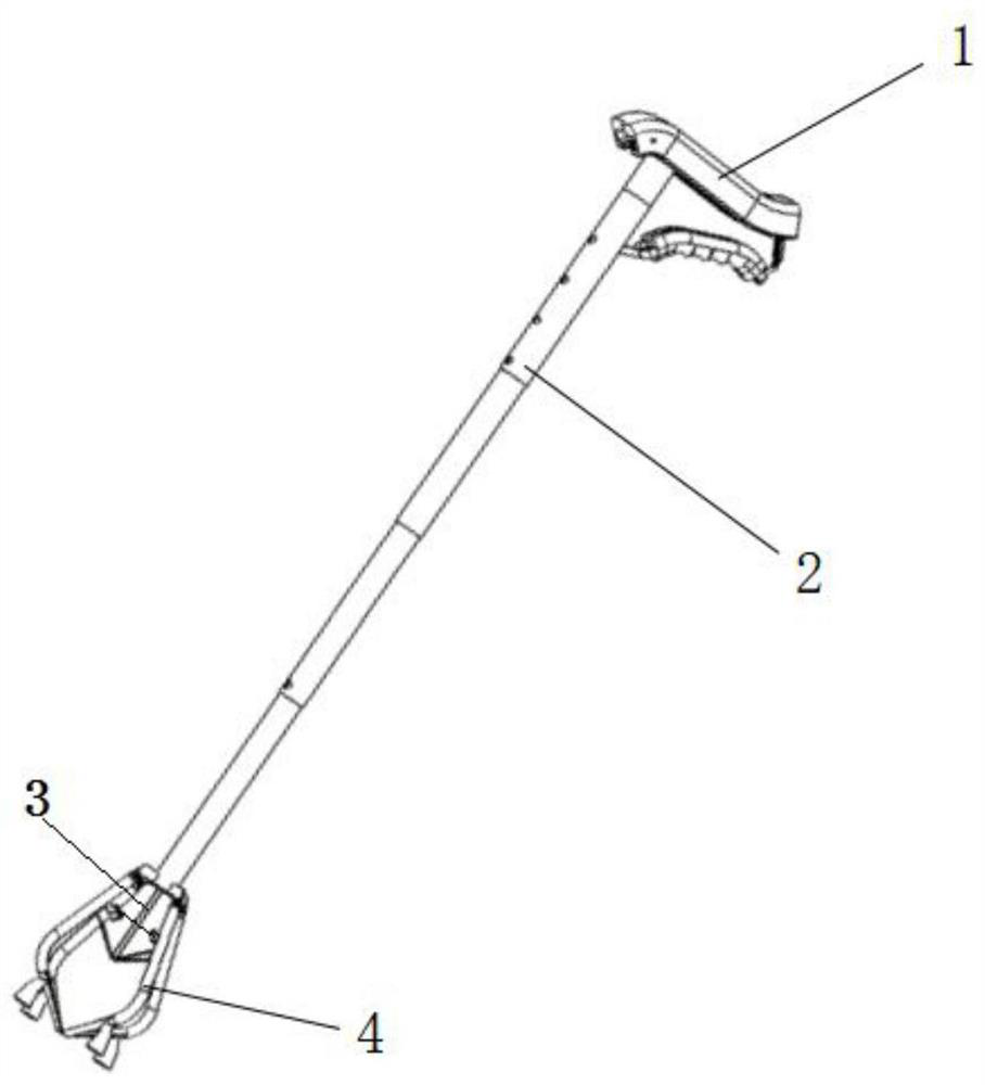
[0041] This embodiment discloses a graspable multifunctional crutch, which includes a handle 1 , an external telescopic rod 2 , an internal control rod 3 and a handle part 4 .
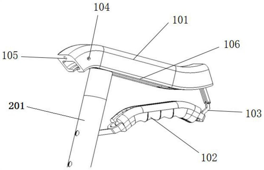
[0042] The handle 1 includes a main handle 101, an auxiliary handle 102 and a main and auxiliary handle connecting rod 103. The main handle 101 is located directly above the auxiliary handle 102, and the two ends of the main handle 101 are marked as a front end and a rear end. see figure 2 Or 3, the front end of the main handle 101 is provided with a light bulb button 104 , and the rear end is provided with a positioning button 107 .
[0043] see figure 2 , the lower surface of the main handle 101 is connected with the main and auxiliary handle connecting rod 103, the GPS positioning chip 106 and the vertical external telescopic rod 2, the main and auxiliary handle connecting rod 103 and the external telescopic rod 2 are respectively close to the rear end of the main handle 101 and front end. The ...
Embodiment 2
[0064] This embodiment discloses a graspable multifunctional crutch, which includes a handle 1 , an external telescopic rod 2 , an internal control rod 3 and a handle part 4 .
[0065] The handle 1 includes a main handle 101, an auxiliary handle 102 and a main and auxiliary handle connecting rod 103. The main handle 101 is located directly above the auxiliary handle 102, and the two ends of the main handle 101 are marked as a front end and a rear end. see figure 2 Or 3, the front end of the main handle 101 is provided with a light bulb button 104 , and the rear end is provided with a positioning button 107 .
[0066] see figure 2 , the lower surface of the main handle 101 is connected with the main and auxiliary handle connecting rod 103, the GPS positioning chip 106 and the vertical external telescopic rod 2, the main and auxiliary handle connecting rod 103 and the external telescopic rod 2 are respectively close to the rear end of the main handle 101 and front end. The ...
Embodiment 3
[0077] The main structure of this embodiment is the same as that of Embodiment 2. Further, the first-stage telescopic rod 201 is provided with groove I along its length direction, the second-stage telescopic rod 202 is provided with groove II along its length direction, and the third-stage telescopic rod 203 is provided with groove II along its length direction. Groove III is arranged along its length direction, and groove IV is arranged along the length direction of the three-stage telescopic rod 203 .
[0078] see Image 6 , the groove I of the primary telescopic rod 201 is embedded in the groove II of the secondary telescopic rod 202, the lower end of the groove II is embedded in the upper end of the groove III, and the lower end of the groove III is embedded in the upper end of the groove IV. It is ensured that the first-stage telescopic rod 201 , the second-stage telescopic rod 202 , the third-stage telescopic rod 203 and the fourth-stage telescopic rod 204 do not rotate ...
PUM
 Abstract
Description
Claims
Application Information
 - R&D
- Intellectual Property
- Life Sciences
- Materials
- Tech Scout
- Unparalleled Data Quality
- Higher Quality Content
- 60% Fewer Hallucinations
Browse by: Latest US Patents, China's latest patents, Technical Efficacy Thesaurus, Application Domain, Technology Topic, Popular Technical Reports.
© 2025 PatSnap. All rights reserved.Legal|Privacy policy|Modern Slavery Act Transparency Statement|Sitemap|About US| Contact US: help@patsnap.com


