
System and method for trajectory accuracy compensation of industrial robots based on kinematics analysis

An industrial robot and motion track technology, applied in manipulators, manufacturing tools, program-controlled manipulators, etc., can solve the problems of difficulty in meeting the demand for high motion track accuracy, few systems and methods, etc., achieve high practical value and improve motion track accuracy , low cost effect

Active Publication Date: 2021-06-15
ZHEJIANG SCI-TECH UNIV
View PDF5 Cites 0 Cited by
  • Summary
  • Abstract
  • Description
  • Claims
  • Application Information

AI Technical Summary

Problems solved by technology

At present, most of the methods and technical research on the improvement of robot precision at home and abroad are realized by the calibration method based on spatial position points. There are relatively few systems and methods for improving the accuracy of specific motion trajectories, and it is difficult to meet the needs of industrial robots in the field of precision manufacturing and assembly. The demand for high motion trajectory accuracy in the application

Method used


Image

  • System and method for trajectory accuracy compensation of industrial robots based on kinematics analysis
  • System and method for trajectory accuracy compensation of industrial robots based on kinematics analysis
  • System and method for trajectory accuracy compensation of industrial robots based on kinematics analysis

Examples


Embodiment Construction

[0048] The present invention will be described in detail below in conjunction with the accompanying drawings and embodiments.

[0049] The embodiment implemented according to the complete method of the content of the present invention is as follows:

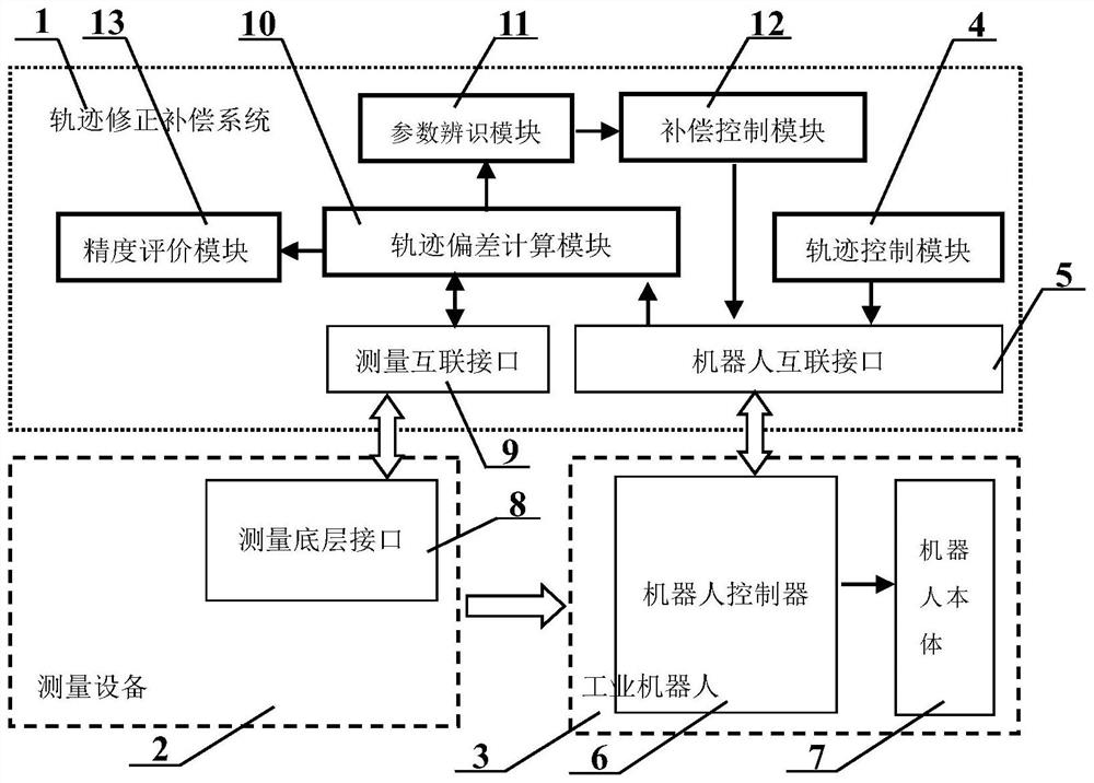
[0050] In this embodiment, the measurement device 2 is a laser tracker, specifically the RADIAN-API tracker of Precision Engineering Company, which uses laser interferometry to measure track data. Its linear measurement range is 40m, and its angular resolution is 0.018as. The resolution is 1μm, and the maximum tracking speed is 6m / s. The industrial robot 6 used in the trajectory correction and compensation experiment is the SR4C six-degree-of-freedom robot of Hangzhou Xinsong, with a load of 4kg and a repeat positioning accuracy of ±0.03mm. The robot has a robot controller 6 with an open interface, and the controller uses It is designed and implemented based on open-source RT-Linux, and the trajectory data from the trajectory co...


PUM


Abstract

The invention discloses an industrial robot track precision compensation system and method based on kinematics analysis. The robot interconnection interface and the measurement interconnection interface are respectively connected to the robot controller and the measurement bottom layer interface. Both the robot interconnection interface and the measurement interconnection interface are connected to the input terminal of the trajectory deviation calculation module, and the output terminals of the trajectory deviation calculation module are respectively connected to the parameter identification module and The accuracy evaluation module, the output terminal of the parameter identification module is connected to the robot interconnection interface through the compensation control module, and the trajectory control module is connected to the robot interconnection interface; the method establishes the motion trajectory deviation model of the industrial robot, and then uses the robot trajectory data measured by the measuring equipment to carry out Model parameter identification, and finally the identified error data is used for parameter compensation of the robot kinematics model. The invention compensates the motion track deviation of the industrial robot from the perspective of kinematics analysis, improves the motion track accuracy of the robot, has low cost and is easy to implement.

Description

technical field [0001] The present invention relates to a motion control system and method in the field of robot technology, in particular to an industrial robot trajectory accuracy compensation system and method based on kinematics analysis, which improves the motion trajectory accuracy by compensating the parameter error of the kinematics model . Background technique [0002] The trajectory accuracy of industrial robots is an important technical index for evaluating the performance of robots. At present, robots in industrial applications generally have high repeatability positioning accuracy, but with the improvement of industrial production automation and precision manufacturing precision requirements, in addition to requiring robots to have high positioning accuracy, there are also requirements for the accuracy of their motion trajectory. Higher and higher, such as in applications such as precision laser cutting, precision laser welding and advanced manufacturing and eq...

Claims


Application Information

Patent Timeline
Patent Type & Authority Patents(China)
IPC IPC(8): B25J9/16
CPCB25J9/16B25J9/1628B25J9/1664
Inventor 张恩政陈本永唐尧
Owner ZHEJIANG SCI-TECH UNIV
Learn More