
Robot joint motor synchronization control system and method

A robot joint, synchronous control technology, applied in the field of synchronous control system and robot joint motor synchronous control system, can solve the problems of clock running asynchronous, clock drift, delay, etc., to achieve the effect of improving synchronization performance and improving the accuracy of motion trajectory

Active Publication Date: 2016-08-24
SIASUN ROBOT & AUTOMATION LIMITED BY SHARE
View PDF4 Cites 4 Cited by
  • Summary
  • Abstract
  • Description
  • Claims
  • Application Information

AI Technical Summary

Problems solved by technology

[0003] Since the drivers of each joint motor have local clocks that run independently, there is a difference between the local clocks when the system starts; during operation, because the local clocks of each driver use independent clock sources, their timing cycles drift , which in turn causes the clock to run asynchronously and cause clock drift; communication data will also generate a certain delay when it is transmitted between the drivers of the joint motors, and between the controller and the driver
The combined effects of the above factors make the movement of the motors of each joint asynchronous, and eventually cause a large error in the trajectory of the robot's end.

Method used


Image

  • Robot joint motor synchronization control system and method
  • Robot joint motor synchronization control system and method

Examples


Embodiment 1

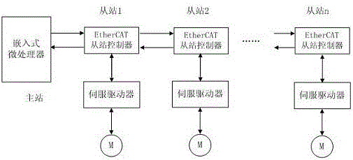
[0045] Embodiment 1: as figure 1 with figure 2 As shown, a robot joint motor synchronous control system, including embedded microprocessor, servo driver, EtherCAT bus and EtherCAT slave station controller;

[0046] The embedded microprocessor is provided with an Ethernet controller, which is connected with the EtherCAT slave station controller through the EtherCAT bus, and the EtherCAT slave station controller is connected with the servo driver.

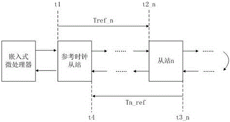
[0047] The first EtherCAT slave connected to the embedded microprocessor as a reference clock slave;

[0048] The EtherCAT slave station controller contains 4 data transceiver ports, and the receiving time of each port is stored in 4 different registers, and the local clock time when the data frame arrives at the port 0-4 is respectively saved in the port 0-4 register;

[0049] Described EtherCAT slave station controller contains local system time register, stores the local system time when each data frame arrives;

[0050] The E...


PUM


Abstract

The invention relates to a synchronization control system, especially a robot joint motor synchronization control system and method, and belongs to the field of industrial automatic control. The system comprises an embedded microprocessor, a servo driver, an EtherCAT bus, and an EtherCAT slave station controller. The system and method greatly improve the performance of synchronization among all slave stations, and the synchronization precision reaches an ns level, thereby enabling all robot joints to be able to achieve the highly synchronous movement, and greatly improving the precision of a tail end movement track of a robot.

Description

technical field [0001] The invention relates to a synchronous control system, in particular to a robot joint motor synchronous control system and a method thereof, belonging to the field of industrial automation control. Background technique [0002] With the advancement of the "machine replacement" strategy, more and more automated production lines have integrated industrial robots to replace human operations. There are more and more application fields of industrial robots, and the requirements for control precision are getting higher and higher. The terminal pose of an industrial robot is produced by the multi-shutdown cooperative motion compound, and the synchronous control accuracy of each joint motor is a key factor affecting the accuracy of the terminal motion trajectory. [0003] Since the drivers of each joint motor have local clocks that run independently, there is a difference between the local clocks when the system starts; during operation, because the local clo...

Claims


Application Information

Patent Timeline
IPC IPC(8): G05B19/418
CPCY02P90/02G05B19/4186
Inventor 李正刚徐进荣陈立金晶刘翠苹
Owner SIASUN ROBOT & AUTOMATION LIMITED BY SHARE
Learn More