Article fixation apparatus and article fixation structure assembly method
A technology for fixing devices and articles, applied in the directions of transportation and packaging, additional accessories, vehicle parts, etc., can solve the problems of easy deformation, complicated sealing structure of closed gaps, etc., and achieve the effect of improving installation workability
Pending Publication Date: 2020-06-19
HONDA MOTOR CO LTD
6 Cites 0 Cited by
AI-Extracted Technical Summary
Problems solved by technology
However, the roof panel is easily deformed because it is a thin plate, and the roof beam is a long member extending in the front and rear directi...
Method used
[0068] In this way, the reinforcing member 16 is joined at the portion 43 of the lower surface 14c of the roof panel 14 that is covered by the roof rail 22 from above the vehicle body. Thus, the roof rail 22 can cover the site 43 where the reinforcing member 16 is joined to the roof panel 14 (for example, welding scars during joining by spot welding) from above the vehicle body, thereby ensuring appearance (beautiful appearance).
[0093] Furthermore, the reinforcing member 16 is joined to the lower surface 14c of the top plate 14 around the first through hole 41. As a result, the roof panel 14 around the first through hole 41 which receives the relatively large load F1 input from the protrusion 67 and the roof rail 22 can be reinforced with the reinforcing member 16 . Thereby, the thickness dimension of the whole roof panel 14 can be reduced, and weight reduction of the roof panel 14 (that is, a vehicle body) can be achieved.
[0095] The first packing 62 is provided in the gap 87 between the first through hole 41 and the protrusion 67. As the first sealing material 62 , for example, a sealing material, a gasket, and the like that are applied in a liquid state at the time of use and cured at room temperature after the application are mentioned. By providing the first packing 62 in the gap 87 between the first through hole 41 and the protrusion 67 , it is possible to suppress intrusion of water from the gap 87 into the vehicle interior of the roof panel 14 . Thereby, it is possible to obtain a sealing effect in which water intrusion from the roof panel 14 into the vehicle interior can be suppressed with a simple structure.
[0098] In this way, by providing the second sealing material 63 in an annular shape throughout the entire circumference of the first through hole 41 and the second through hole 47, it is possible to utilize the second sealing material 63 throughout the entire circumference of the first through hole 41. Between the raised portion 16c and the lower surface 14c of the top plate 14 is circumferentially blocked. Thereby, a sealing effect on the gap 87 between the first through hole 41 and the protruding portion 67 can be obtained, and a reliable sealing effect can be further enhanced with a simple sealing structure.
[0106] Furthermore, by providing the first packing 62 in the gap 87 between the first through hole 41 and the protrusion 67, infiltration of water into the vehicle interior of the roof panel 14 from the gap 87 is suppressed. Accordingly, it is possible to obtain a sealing effect that prevents water from entering the vehicle interior from the roof panel 14 with a simple structure.
[0113] According to the vehicle body superstructure 100, by setting the support member 102 as a cross member erected on the left roof rail 26 and the right roof rail, the right and left roof rails 26 can be utilized as a pair. The supporting member 102 supports both ends. Accordingly, the rigi...
Abstract
An article fixation apparatus 20 includes an article attachment member 60 and a first seal material 62. The article attachment member includes a protrusion part 67 which protrudes toward a vehicle outside via a penetration hole 41 of a roof panel 14 from a vehicle inside of the roof panel and which fixes an article 22 and a head part seat surface 66 that is joined to a lower surface side 16d of areinforcement member 16. The first seal material prevents water permeation to the vehicle inside of the roof panel from a gap between the penetration hole and the protrusion part.
Application Domain
Supplementary fittings
Technology Topic
EngineeringStructural engineering +1
Image
Examples
- Experimental program(8)
Example
[0054] (first embodiment)
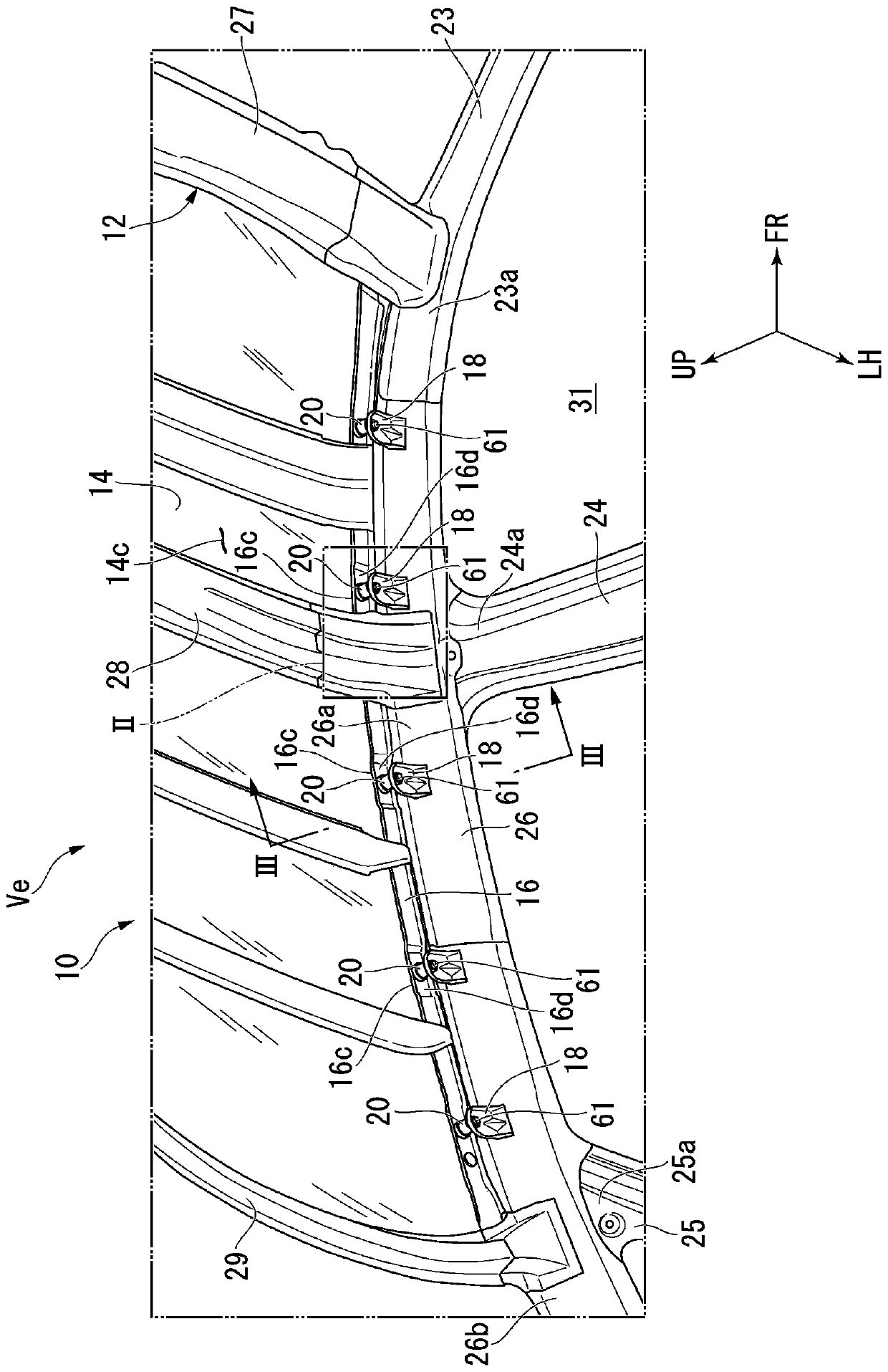
[0055] like figure 1 , figure 2 As shown, a vehicle body superstructure 10 has a body frame member 12, a roof (body panel, first panel) 14, a reinforcement member 16, a plurality of support members (second panel) 18, a plurality of article securing devices 20, and a roof rail ( Item) 22 (refer to image 3 ).
[0056] The vehicle body frame member 12 includes a front pillar 23 , a center pillar 24 , a rear pillar 25 , a roof rail 26 , a front roof cross member 27 , a center roof cross member 28 , and a rear roof cross member 29 .
[0057] The front pillar 23 is erected on the front left side of the cabin 31 and is formed in a closed cross section. The front roof cross member 27 is spanned over the upper end portion 23a of the left front pillar 23 and the upper end portion (not shown) of the right front pillar along the vehicle width direction.
[0058] The center pillar 24 is erected on the left side of the center of the cabin 31 and has a closed cross section. The rear pillar 25 is erected on the rear left side of the compartment 31 and is formed in a closed cross section.
[0059] A roof rail 26 is connected to an upper end portion 23 a of the front pillar 23 , an upper end portion 24 a of the center pillar 24 , and an upper end portion 25 a of the rear pillar 25 .
[0060] like image 3 As shown, the roof rail 26 includes, for example, an outer rail 34 and an inner rail 35 . The outer side rail 34 forms an upper portion of the roof rail 26 and has a first outer flange 34 a protruding outward in the vehicle width direction and a first inner flange 34 b protruding inward in the vehicle width direction. The inner side rail 35 forms a lower portion of the roof rail 26 and has a second outer flange 35 a protruding outward in the vehicle width direction and a second inner flange 35 b protruding inward in the vehicle width direction.
[0061] The first outer flange 34a and the second outer flange 35a are engaged with each other. The first inner flange 34b and the second inner flange 35b are engaged with each other. Thus, the roof rail 26 is formed into a closed cross section by the outer rail 34 and the inner rail 35 .
[0062] return figure 1 The central roof cross member 28 is erected along the vehicle width direction at a portion 26a of the left roof rail 26 that is closer to the center of the vehicle body in the front-rear direction and a portion of the right roof rail member that is closer to the center of the vehicle body in the front-rear direction. (not shown). The rear roof cross member 29 is erected over the vehicle body rear portion 26b of the left roof rail 26 and the vehicle body rear portion (not shown) of the right roof rail along the vehicle width direction.
[0063] The roof panel 14 is supported by roof rails 26 , front roof rails 27 , center roof rails 28 , and rear roof rails 29 .
[0064] The roof panel 14 is formed in a rectangular shape in plan view along the outer periphery of the left roof rail 26 , the right roof rail, the front roof rail 27 , and the rear roof rail 29 .
[0065] like image 3 As shown, the left side (outer side) 14a of the top plate 14 is formed along the inner side 34c of the outer stringer 34, and the left side 14a and the inner side 34c are brazed (brazed) via a brazed joint 38 join. The roof panel 14 has: a roof rail mounting portion 14b along the left side portion 14a, and a plurality of first through-holes arranged at intervals along the front and rear direction of the vehicle body on the roof rail mounting portion 14b. Hole (through hole) 41 (also refer to Figure 4 ).
[0066] like figure 1 , image 3 As shown, on the lower surface 14c of the top plate 14, the reinforcing member 16 is along the left side portion 14a (see also image 3 ) and extend in a band shape to the front and rear directions of the vehicle body. The outer side 16a of the reinforcing member 16 is bent downward. The inner side 16b of the reinforcing member 16 is bent downward. On the reinforcing member 16, a plurality of raised portions 16c are formed at intervals along the vehicle body front-rear direction. A plurality of raised portions 16c engage with the lower surface 14c of the top plate 14 .
[0067] like image 3 , Figure 4 As shown, the raised portion 16c of the reinforcing member 16 is located at a portion 43 of the lower surface 14c of the roof panel 14 located around the first through hole 41 and covered by the roof rail 22 from above the vehicle body, for example, by spot welding or bonding. agent for bonding.
[0068] In this way, the reinforcing member 16 is joined to the portion 43 of the lower surface 14c of the roof panel 14 covered by the roof rail 22 from above the vehicle body. Thus, the roof rail 22 can cover the site 43 where the reinforcing member 16 is joined to the roof panel 14 (for example, welding scars during joining by spot welding) from above the vehicle body, thereby ensuring appearance (beautiful appearance).
[0069] Moreover, the second packing 63 is provided over the entire circumference of the first through hole 41 between the raised portion 16 c of the reinforcement member 16 and the lower surface 14 c of the top plate 14 . The second sealing member 63 will be described in detail later.
[0070] The raised portion 16c has a second through hole 47 . The second through hole 47 is arranged below the first through hole 41 of the top plate 14 .
[0071] A plurality of support members 18 are arranged at intervals below the plurality of raised portions 16c (see also figure 1 ). The plurality of support members 18 are joined to an inner side portion (mounting portion on the vehicle body Ve side) 35c of the inner side member 35 . Hereinafter, the attachment portion 35c on the vehicle body Ve side is referred to as "the attachment portion 35c on the vehicle body side". An article securing device 20 is interposed between the reinforcement member 16 and the support member 18 .
[0072] like figure 2 , image 3 As shown, the support member 18 has a support mounting portion 51 , a base end portion 52 , a peripheral portion 53 and a gusset 54 . The support member 18 is integrally formed with the support attachment part 51, the base end part 52, the peripheral part 53, and the brace 54 with one plate material, for example.
[0073] The support mounting portion 51 is arranged below the raised portion 16c of the reinforcement member 16 and is formed flatly along the raised portion 16c. The support attachment portion 51 is configured, for example, such that the front end is formed in a curved shape protruding inward in the vehicle width direction, and the base end is formed in a linear shape extending in the vehicle front-rear direction. A base end portion 52 is formed at the base end of the support mounting portion 51 . The supporting mounting part 51 has a mounting hole 56 at a position close to the front end.
[0074] The base end portion 52 is bent downward from the base end of the support attachment portion 51 along the vehicle body side attachment portion 35c. The support member 18 is cantilever-supported by the vehicle body side mounting part 35c by joining the base end part 52 to the vehicle body side mounting part 35c. A peripheral portion 53 is formed around the support attachment portion 51 and the base end portion 52 . The peripheral portion 53 is bent downward from the periphery of the support mounting portion 51 and bent toward the inside in the vehicle width direction from the periphery of the base end portion 52 . The support mounting portion 51 is reinforced by a peripheral portion 53 .
[0075]A brace 54 is formed on the support attachment portion 51 and the base end portion 52 . The brace 54 is provided on the base end portion 52 and the support mounting portion 51 . The lower side 54 a of the brace 54 extends upwardly inward in the vehicle width direction (vehicle width inner direction) from the base end portion 52 to a portion 51 a of the support mounting portion 51 abutting the mounting hole 56 . In this way, in the state where the support member 18 is cantilevered by the vehicle body side mounting portion 35c, by providing the brace 54 on the support member 18, the brace 54 is used to reinforce the support member 18, so that the support member 18 can be ensured. Strength, rigidity.
[0076] like image 3 , Figure 4 As shown, the support attachment part 51 of the support member 18 is arrange|positioned at intervals below the raised part 16c of the reinforcement member 16. As shown in FIG. The article fixing device 20 is interposed between the protruding portion 16 c and the support mounting portion 51 .
[0077] The article fixing device 20 includes a roof rail attachment member 60 (article attachment member), fastening bolts 61 , a first seal 62 , and a second seal 63 . The roof rail mounting member 60 includes an adjustment mechanism 65 , a head support surface 66 , and a protrusion 67 . The adjustment mechanism 65 includes a fitting female member (one member) 71 and a fitting male member (the other member) 72 .
[0078] The fitting female member 71 has a cylindrical portion 75 and an overhanging top 76 . The cylindrical part 75 is formed in a hollow cylindrical shape by the cylindrical wall 75a, and the internal thread 78 is formed in the inner peripheral surface of the cylindrical wall 75a.
[0079] A protruding top portion 76 is integrally provided on the top portion 75 b of the cylindrical portion 75 . The top portion 75b of the cylindrical portion 75 is closed by a protruding top portion 76 . The protruding top portion 76 is formed in a disc shape, and protrudes outward in the radial direction from the cylinder wall 75 a of the cylinder portion 75 . The protruding top portion 76 has a circular head support surface 66 formed on its upper surface. The protruding portion 67 protrudes from the center of the head support surface 66 toward the side opposite to the cylindrical portion 75 . The protruding portion 67 is constituted by an external thread portion. The head support surface 66 and the protrusion 67 will be described in detail later.
[0080] The fitting male member 72 is fitted to the internal thread 78 of the cylindrical portion 75 of the fitting female member 71 . The fitting male member 72 includes a convex screw hole 81 penetrating through the fitting male member 72 coaxially with the fitting male member 72 , a protruding portion 82 , and an overhanging bottom 83 . An external thread 82 a capable of screwing into the internal thread 78 of the cylindrical portion 75 is formed on the outer peripheral surface of the protruding portion 82 . When the external thread 82a of the protruding part 82 is screwed into the internal thread 78 of the cylindrical part 75, the protruding part 82 is fitted into the cylindrical part 75 freely. Thereby, the axial dimension of the adjustment mechanism 65 can be adjusted.
[0081] A protruding bottom 83 is integrally provided on the bottom 82b of the protruding portion 82 . The protruding bottom 83 is formed in a disc shape and protrudes radially outward from the outer peripheral wall of the protruding portion 82 . The protruding bottom portion 83 is placed on the support attachment portion 51 of the support member 18 . In this state, the protrusion threaded hole 81 is disposed above the mounting hole 56 of the support mounting portion 51 . The fastening bolt 61 passes through the mounting hole 56 from below, and the fastening bolt 61 passed through is screwed into the convex threaded hole 81 . As a result, the fitting convex member 72 is fixed to the support mounting portion 51 . In other words, the support attachment portion 51 is fastened to the fitting convex member 72 by the fastening bolt 61 . That is, the adjustment mechanism 65 is fixed to the vehicle body side attachment portion 35 c via the support member 18 .
[0082] The mounting hole 56 of the support member 18 is formed in a shape allowing position adjustment of the fastening bolt 61 in a direction intersecting the axial direction of the fastening bolt 61 in a state where the fastening bolt 61 penetrates therethrough. Specifically, the mounting hole 56 is formed, for example, so that its inner diameter is larger than the outer diameter of the fastening bolt 61 to allow position adjustment (so-called free-sized hole). As another example, the mounting hole 56 may be formed as a long hole to allow position adjustment of the fastening bolt 61 in a direction intersecting the axial direction of the fastening bolt 61 .
[0083] The head support surface 66 and the protrusion 67 are integrally provided on the protruding top portion 76 of the adjustment mechanism 65 . The head support surface 66 is formed in a circular shape by protruding from the upper surface of the top portion 76 . The head support surface 66 is joined to the lower surface of the reinforcement member 16 (specifically, the raised portion 16 c ) over the entire circumference of the first through hole 41 via the annular joint portion 85 by, for example, annular projection welding, an adhesive, or the like. 16d. As a result, the gap 87 between the head support surface 66 and the lower surface 16 d of the protruding portion 16 c is closed by the joint portion 85 over the entire circumference outside the gap 87 between the first through hole 41 and the protrusion portion 67 .
[0084] The protrusion 67 protrudes from the head support surface 66 of the protrusion 67 coaxially with the fitting female member 71 . The protruding portion 67 is constituted by an external thread portion. The protrusion 67 passes through the second through hole 47 of the reinforcing member 16 and the first through hole 41 of the roof panel 14 from the vehicle inner side of the reinforcing member 16 toward the vehicle outer side of the roof panel 14 . The roof rail 22 is attached to the protrusion 67 protruding upward from the roof panel 14 .
[0085] Specifically, a base attachment hole 89 is formed in the base 22 a of the roof rail 22 . The protrusion 67 penetrating through the base attachment hole 89 protrudes above the base 22a. The roof rail 22 is attached to the protrusion 67 and fixed to the upper surface of the roof panel 14 by screwing the nut 91 to the protrusion 67 protruding upward from the base 22 a. In this state, a seal 92 is interposed between the inner side of the roof rail 22 and the upper surface of the roof panel 14 . In addition, a packing 92 is interposed between the outer side of the roof rail 22 and the upper surface of the roof panel 14 .
[0086] In addition, the protrusion 67 of the roof rail attachment member 60 protrudes toward the vehicle outer side of the roof panel 14 . Accordingly, when the roof rail 22 is attached to the roof panel 14 , by fitting the base mounting hole 89 of the roof rail 22 into the protrusion 67 , the protrusion 67 can also be used as a positioning reference for the roof rail 22 . As a result, the installation workability when the roof rail 22 is attached to the upper surface of the roof panel 14 can be improved.
[0087] It is considered that the position of the vehicle body side mounting portion 35 c may be shifted due to, for example, an assembly tolerance when assembling the vehicle body Ve. In addition, it is considered that the position of the roof panel 14 is shifted when the roof panel 14 is attached to the roof rail 26 by brazing. Therefore, it is considered that the relative positions of the support member 18 and the top plate 14 are displaced. Therefore, the adjustment mechanism 65 is interposed between the support member 18 and the top plate 14 (specifically, the reinforcement member 16). Thus, by adjusting the adjustment mechanism 65 corresponding to the positional deviation between the support member 18 and the top plate 14 , the positional deviation between the support member 18 and the top plate 14 can be absorbed by the adjustment mechanism 65 .
[0088] Specifically, the fitting female member 71 of the adjustment mechanism 65 is joined to the top plate 14 via the reinforcement member 16 , and the fitting male member 72 of the adjustment mechanism 65 is fixed to the vehicle body side attachment portion 35 c via the support member 18 . Accordingly, by adjusting the screwed state of the adjustment mechanism 65, it is possible to absorb the positional displacement of the roof panel 14 in the vertical direction when the roof panel 14 is brazed to the roof rail 26, and to fix the support member 18 to the vehicle body side. The position of the support member in the up-down direction is shifted when the portion 35c is located.
[0089] In addition, it is considered that in a state where the roof panel 14 is attached to the roof rail 26 and the support member 18 is attached to the vehicle body side attachment portion 35 c, the support member 18 and the roof panel 14 are misaligned in a direction intersecting the axial direction of the fastening bolt 61 . shift.
[0090] Therefore, the attachment hole 56 of the support member 18 is formed to allow positional adjustment of the fastening bolt 61 in a direction intersecting the axial direction. Thereby, by adjusting the position of the fastening bolt 61 according to the relative deviation between the support member 18 and the top plate 14, the deviation between the support member 18 and the top plate 14 can be absorbed by using an attachment hole.
[0091] Furthermore, the adjustment mechanism 65 is integrally provided with a protrusion 67 , and the roof rail 22 is fixed to the roof panel 14 by the protrusion 67 . Accordingly, the load F1 input from the roof rail 22 which is a relatively heavy load can be satisfactorily transmitted to the adjustment mechanism 65 via the protrusion 67 as indicated by the arrow A. As shown in FIG. Thereby, the load F1 input from the roof rail 22 can be satisfactorily received by the adjustment mechanism 65 as a whole.
[0092] In addition, the protrusion 67 is integrally provided on the fitting female member 71 of the adjustment mechanism 65 , and the fitting female member 71 is screwed to the fitting male member 72 of the adjustment mechanism 65 . Thereby, the protrusion part 67, the fitting female member 71, and the fitting male member 72 can be integrated. Accordingly, the load F1 input from the roof rail 22 can be satisfactorily transmitted to the adjustment mechanism 65 via the protrusion 67 .
[0093] Furthermore, the reinforcing member 16 is joined to the lower surface 14 c of the top plate 14 around the first through hole 41 . As a result, the roof panel 14 around the first through hole 41 which receives the relatively large load F1 input from the protrusion 67 and the roof rail 22 can be reinforced with the reinforcing member 16 . Thereby, the thickness dimension of the whole roof panel 14 can be reduced, and weight reduction of the roof panel 14 (that is, a vehicle body) can be achieved.
[0094] Moreover, by providing the brace 54 in the support member 18, the support member 18 is reinforced with the brace 54. As shown in FIG. Accordingly, when the load F1 input from the roof rail 22 is transmitted to the support member 18 via the adjustment mechanism 65 , the transmitted load F2 can be satisfactorily received by the support member 18 . Thereby, the load F2 transmitted to the support member 18 can be satisfactorily transmitted to the vehicle body Ve via the support member 18 and the vehicle body side attachment part 35c.
[0095] The first packing 62 is provided in the gap 87 between the first through hole 41 and the protrusion 67 . As the first sealing material 62 , for example, a sealing material, a gasket, and the like that are applied in a liquid state at the time of use and cured at room temperature after the application are mentioned. By providing the first packing 62 in the gap 87 between the first through hole 41 and the protrusion 67 , it is possible to suppress intrusion of water from the gap 87 into the vehicle interior of the roof panel 14 . Thereby, it is possible to obtain a sealing effect in which water intrusion from the roof panel 14 into the vehicle interior can be suppressed with a simple structure.
[0096] In addition, the head support surface 66 is joined to the reinforcing member 16 (specifically, over the entire circumference of the first through hole 41 and the second through hole 47 ) via the annular joint portion 85 by, for example, annular projection welding, an adhesive, or the like. is the lower surface 16d of the raised portion 16c). Thus, it is possible to obtain a ring-shaped gap over the entire circumference of the outer side of the gap 87 between the first through hole 41 and the protruding portion 67 with a simple structure of joining the head support surface 66 to the lower surface 16d of the protruding portion 16c. Sealing effect. Thereby, a reliable sealing effect can be further improved with a simple sealing structure.
[0097] Furthermore, a second packing 63 is provided annularly over the entire circumference of the first through hole 41 and the second through hole 47 between the raised portion 16 c and the lower surface 14 c of the top plate 14 . As the second sealing material 63 , for example, a sealing material that is applied in a liquid state at the time of use and cured at normal temperature after the application, may be mentioned.
[0098] In this way, by providing the second packing 63 in an annular shape over the entire circumference of the first through hole 41 and the second through hole 47 , it is possible to close the entire circumference of the first through hole 41 by the second seal 63 . between the raised portion 16c and the lower surface 14c of the top plate 14 . Thereby, a sealing effect on the gap 87 between the first through hole 41 and the protruding portion 67 can be obtained, and a reliable sealing effect can be further enhanced with a simple sealing structure.
[0099] Next, refer to image 3 , Figure 4 A method of assembling the article fixing device 20 of the first embodiment will be described.
[0100] like image 3 , Figure 4 As shown, in the first step, by screwing the external thread 82a of the fitting male member 72 and the internal thread 78 of the fitting female member 71 of the adjustment mechanism 65, the fitting female member 71 and the fitting male member are screwed together. 72 (that is, the adjustment mechanism 65) is integrally connected.
[0101]A protrusion 67 is integrally provided on the adjustment mechanism 65 . The protrusion 67 is made to protrude from the second through hole 47 of the reinforcing member 16 (specifically, the raised portion 16c). After the protruding portion 67 protrudes from the second through hole 47 , the head rest surface 66 is joined to the lower surface 16 d of the raised portion 16 c via the joint portion 85 together with the adjustment mechanism 65 . By bonding the head support surface 66 to the lower surface 16d of the raised portion 16c, the protrusion 67 protrudes from the first through hole 41 of the top plate 14 to the vehicle outer side.
[0102] In the second step, the raised portion 16c of the reinforcing member 16 is fixed to the lower surface 14c of the roof plate 14 with the protrusion 67 protruding outward from the first through hole 41 of the roof plate 14 . Specifically, the raised portion 16 c is joined at a portion 43 of the lower surface 14 c of the roof panel 14 located around the first through hole 41 and covered by the roof rail 22 from above the vehicle body.
[0103] In the third step, the adjustment mechanism 65 is fixed to the support member 18 . Specifically, the protruding bottom portion 83 of the adjustment mechanism 65 is placed on the support attachment portion 51 of the support member 18 . After placing the protruding bottom portion 83 on the support mounting portion 51 , the fastening bolt 61 is passed through the mounting hole 56 of the support mounting portion 51 from below, and the threaded fastening bolt 61 is screwed into the convex screw hole 81 . Thereby, the adjustment mechanism 65 is fixed to the support attachment part 51. As shown in FIG.
[0104] In this state, by providing the first packing 62 in the gap 87 between the first through hole 41 and the protrusion 67 , it is possible to suppress the intrusion of water through the gap 87 .
[0105] According to the assembly method of the article fixing device 20, after the head support surface 66 is fixed to the lower surface 16d of the raised portion 16c together with the adjustment mechanism 65 in the first process, the raised portion 16c (that is, the reinforcement member 16 ) is fixed on the top plate 14. And the adjustment mechanism 65 is fixed to the support member 18 (namely, the support attachment part 51) in a 3rd process. Thereby, assembly can be easily performed so that the adjustment mechanism 65 is interposed between the reinforcement member 16 and the support member 18 in the state which made the protrusion part 67 protrude to the vehicle outer side from the roof panel 14. As shown in FIG.
[0106] Furthermore, by providing the first packing 62 in the gap 87 between the first through hole 41 and the protrusion 67 , infiltration of water into the vehicle interior of the roof panel 14 from the gap 87 is suppressed. Accordingly, it is possible to obtain a sealing effect that prevents water from entering the vehicle interior from the roof panel 14 with a simple structure.
[0107] Next, refer to Figure 5 to Figure 9 The vehicle body superstructures 100 , 110 , and 130 of the second to fourth embodiments will be described. It should be noted that among the vehicle body superstructures 100 , 110 , and 130 of the second to fourth embodiments, the same or similar structural members as those of the vehicle body superstructure 10 of the first embodiment are given the same reference numerals and detailed descriptions are omitted. instruction of.
Example
[0108] (second embodiment)
[0109] like Figure 5 As shown, the vehicle body upper structure 100 includes a support member 102 instead of the support member 18 of the first embodiment, and the other structures are the same as those of the vehicle body upper structure 10 of the first embodiment.
[0110] The support member 102 is a cross member that is mounted on the left roof rail (left frame) 26 and the right roof rail (right frame) (not shown) and extends in the vehicle width direction along the roof panel 14 .
[0111] Examples of the supporting member 102 include a roof arch that reinforces the roof panel 14 and the like, a sunroof frame member that opens and closes the roof, and the like.
[0112] The support member 102 has a support mounting portion 104 at the left end. The support attachment part 104 is provided at intervals below the raised part 16c of the reinforcement member 16 similarly to the support attachment part 51 of 1st Embodiment. The adjustment mechanism 65 is interposed between the raised part 16c of the reinforcement member 16, and the support attachment part 104 similarly to 1st Embodiment.
[0113] According to the vehicle body superstructure 100, by making the support member 102 a cross member spanning the roof rail 26 on the left side and the roof rail on the right side, the support member 102 can be supported by the roof rail 26 on the left and right sides. Support both ends. Accordingly, the rigidity of the support member 102 can be increased, and when the article is the roof rail 22 , the load input from the roof rail 22 can be satisfactorily received by the support member 102 . In addition, when a roof rack is used as an item, luggage is piled on the roof rack. In this case, the support member 102 can satisfactorily bear a relatively large load due to luggage on the roof rack.
[0114] Furthermore, by spanning the support member 102 over the left roof rail 26 and the right roof rail, the support member 102 can satisfactorily receive, for example, input from the left and right roof rail 26 sides. Impact loads from side impacts.
Example
[0115] (third embodiment)
[0116] like Figure 6 ~ Figure 8 As shown, the vehicle body upper structure 110 is provided with a reinforcing member 112 and a roof rail mounting member 113 (item mounting member) instead of the reinforcing member 16 and the roof rail mounting member 60 of the first embodiment, and other structures are the same as those of the vehicle body of the first embodiment. The superstructure 10 is the same.
[0117] The reinforcement member 112 has a roof rail 22 (refer to image 3 ) a plurality of first mounting and fixing portions 115 fixed and a plurality of second mounting and fixing portions 116 for fixing the adjustment mechanism 122 of the roof rail mounting member 113 .
[0118] The first mounting and fixing portion 115 is arranged in a state of being in contact with the lower surface 14 c of the top plate 14 . The fixed portion 121 of the roof rail mounting member 113 is fixed to the first mounting and fixing portion 115 . The second mounting and fixing portion 116 is provided at a position shifted from the first mounting and fixing portion 115 in the front-rear direction of the vehicle body.
[0119] In addition, the second mounting and fixing portion 116 bulges downward relative to the first mounting and fixing portion 115 , and thereby is arranged downwardly at a distance from the lower surface 14 c of the top plate 14 .
[0120] The second mounting and fixing portion 116 has a front inclined portion 117 , a rear inclined portion 118 and a central mounting portion 119 . The front inclined portion 117 extends with a descending slope from the rear end of the first mounting fixing portion 115 toward the rear of the vehicle body. The rear inclined portion 118 is provided at intervals behind the vehicle body of the front inclined portion 117 and extends upwardly from the rear end of the central mounting portion 119 toward the rear of the vehicle body. The central mounting portion 119 is provided between the rear end of the rear inclined portion 118 and the front end of the front inclined portion 117 , and is connected to the rear end of the rear inclined portion 118 and the front end of the front inclined portion 117 . The central attachment portion 119 is arranged parallel to the support attachment portion 51 of the support member 18 .
[0121] The roof rail mounting member 113 includes a fixing portion 121 and an adjustment mechanism 122 . The protrusion 67 and the head support surface 124 are integrally provided on the fixed portion 121 . The protruding portion 67 passes through the first through hole 41 of the top plate 14 and the second through hole 47 of the first mounting and fixing portion 115 (see also Figure 4 ), and protrude upward from the roof plate 14 toward the vehicle outer side. In this state, the head rest surface 124 is engaged with the lower surface 115 a of the first mounting and fixing portion 115 . By attaching the roof rail 22 to the protruding portion 67 , the roof rail 22 is fixed to the upper surface of the roof panel 14 by the fixing portion 121 .
[0122] The adjustment mechanism 122 includes a fitting female member (one member) 126 and a fitting convex member (the other member) 127 . The fitting female member 126 includes the cylindrical portion 75 and the coupling member 128 . The fitting female member 126 is provided, for example, such that the cylindrical portion 75 is disposed below the central mounting portion 119 and the coupling member 128 is disposed above the central mounting portion 119 . , thereby fixing the fitting female member 126 to the central mounting portion 119 .
[0123] Through the internal thread 78 (refer to image 3 ) is screwed to the protruding portion 82 of the fitting male member 72 , whereby the fitting female member 126 and the fitting male member 72 (that is, the adjustment mechanism 122 ) are integrally connected. The fitting male member 72 passes through the convex screw hole 81 of the fitting male member 72 (refer to image 3 ) is fixed to the support attachment portion 51 of the support member 18 by screwing the fastening bolt 61 . In this state, the adjustment mechanism 122 is provided at a position deviated from the fixed portion 121 of the roof rail attachment member 113 in the vehicle front-rear direction.
[0124] According to the vehicle body upper structure 110 , by shifting the adjustment mechanism 122 and the fixing portion 121 in the front-rear direction of the vehicle body, the adjustment mechanism 122 and the fixing portion 121 can be respectively disposed at appropriate positions. Specifically, the fixing portion 121 can be arranged at a position where the roof rail 22 can be well supported (for example, the center of the roof rail 22 ), and the adjustment mechanism 122 can be arranged near the center pillar 24 which is a frame member of the vehicle body Ve.
[0125] Accordingly, the load transmitted from the roof rail 22 to the fixed portion 121 can be well distributed to the reinforcement member 112, and the load transmitted from the fixed portion 121 to the adjustment mechanism 122 via the reinforcement member 112 can be well distributed to the center pillar 24 (that is, Body Ve) transfer. Accordingly, the load input from the roof rail 22 can be satisfactorily received by the vehicle body Ve.
[0126] In addition, the second mounting and fixing portion 116 is arranged at a distance below from the lower surface 14 c of the top plate 14 . Thereby, the central mounting part 119 of the 2nd mounting fixing part 116 can be arrange|positioned parallel to the support mounting part 51 of the support member 18. As shown in FIG. The fitting female member 126 of the adjustment mechanism 122 is fixed to the central attachment portion 119 , and the fitting male member 72 of the adjustment mechanism 122 is fixed to the support attachment portion 51 . Thus, for example, in an embodiment in which the top plate 14 is formed as a curved surface swollen outward from the vehicle body, it is not necessary to provide the adjustment mechanism 122 with a structure corresponding to the curved surface of the top plate 14 , and the adjustment mechanism 122 can be simplified.
[0127] Furthermore, by having the front inclined portion 117 and the rear inclined portion 118 in the second attachment fixing portion 116 , the rigidity of the reinforcing member 112 can be increased by the front inclined portion 117 and the rear inclined portion 118 . Thereby, the load of the roof rail 22 can be satisfactorily transmitted to the central mounting portion 119 via the fixing portion 121 . The load transmitted to the central mounting portion 119 is transmitted to the adjustment mechanism 122 .
PUM


Description & Claims & Application Information
We can also present the details of the Description, Claims and Application information to help users get a comprehensive understanding of the technical details of the patent, such as background art, summary of invention, brief description of drawings, description of embodiments, and other original content. On the other hand, users can also determine the specific scope of protection of the technology through the list of claims; as well as understand the changes in the life cycle of the technology with the presentation of the patent timeline. Login to view more.