

Automobile windshield wiper with spraying function
A technology for automobiles and wipers, used in vehicle maintenance, vehicle cleaning, transportation and packaging, etc., can solve the problems of easily scratched glass, small cleaning area, inconvenient glass surface cleaning, etc. The effect of reducing the area and amplitude of
Inactive Publication Date: 2020-06-19
重庆龙冠机械制造有限公司
View PDF0 Cites 0 Cited by
- Summary
- Abstract
- Description
- Claims
- Application Information
AI Technical Summary
Problems solved by technology
[0003] The existing wiper rotates more to clean, which makes the cleaning area smaller, which is not convenient for cleaning the entire glass surface. At the same time, the glass surface is usually dry and easy to scratch the glass
Method used
View moreImage
Smart ImageViewing Examples

Examples
Embodiment approach
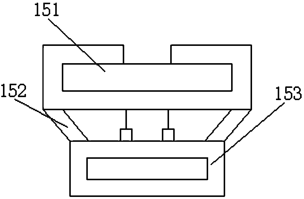
[0021] As a preferred embodiment of the present invention, the storage battery 153 is electrically connected to the energy supply device 15 through two terminals provided on the upper surface.
Login to View More PUM
 Abstract
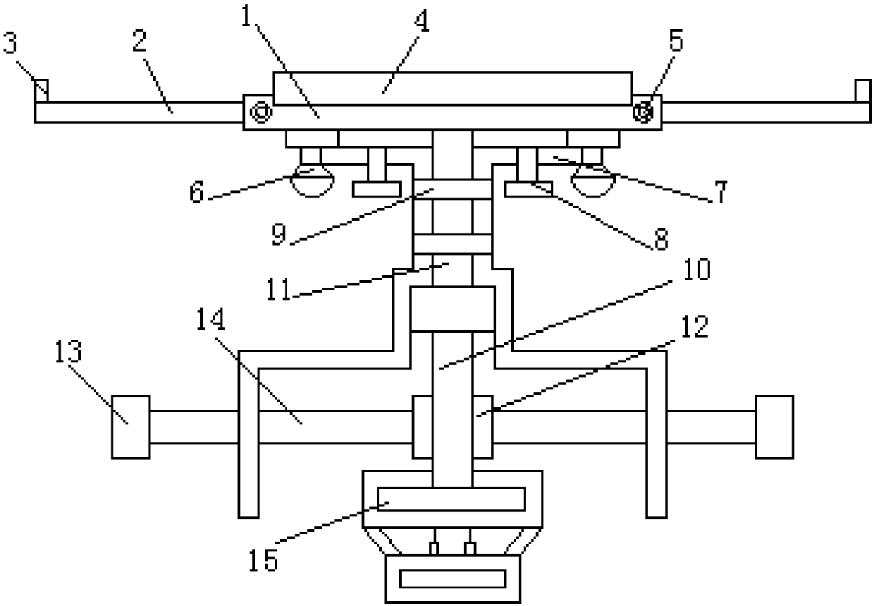
The invention discloses an automobile windshield wiper with a spraying function. The automobile windshield wiper includes a main rod, expansion rods are slidably arranged at the two ends of the main rod, limiting blocks are arranged on the upper surfaces of the outer ends of the two expansion rods, the front ends of the two sides of the main rod are each provided with a locking bolt facilitating locking of the corresponding expansion rod, a rotating shaft is arranged at the lower surface of the main rod, spray heads are arranged on the two sides of the lower surface of the main rod, the two spray heads are communicated with pipelines, the two pipelines are fixed to the rotating shaft through two bandages, the lower end of the rotating shaft is movably connected with a main shaft, and the lower portion of the main shaft penetrates through a middle plate and extends into an energy supply device below the middle plate. A stepping motor drives the main rod to clean up and down, so that themoving amplitude is reduced, and the influence on a driver is avoided; and the expansion rods are arranged in the main rod, so that the whole glass surface is convenient to clean, the cleaning area is increased, and the cleaning efficiency is greatly improved.
Description
technical field [0001] The invention relates to the technical field of cleaning equipment, in particular to an automobile wiper with a spray function. Background technique [0002] The so-called wiper is a tool for simple cleaning on the front glass of a motor vehicle in order to prevent rainwater and other dirt from affecting the line of sight. [0003] Existing windshield brushes are often rotated for cleaning, which makes the cleaning area smaller and inconvenient for cleaning the entire glass surface. Meanwhile, the glass surface is relatively dry and easy to scratch the glass. Contents of the invention [0004] Aiming at the deficiencies in the prior art, the purpose of the present invention is to provide a car wiper with spray function to improve the problems raised in the above-mentioned background technology. The design of the present invention is reasonable and can effectively solve the problems of small cleaning area and easily damaged glass. [0005] In order t...
Claims
Login to View More Application Information
Patent Timeline
 Patent Type & AuthorityApplications(China)
IPC IPC(8): B60S1/34B60S1/52
CPCB60S1/3415B60S1/522
Inventor闫颖涛
Owner重庆龙冠机械制造有限公司