
Balanced multi-path bus insulation monitoring device

An insulation monitoring device and a balanced technology, which is applied in the design field of aerospace measurement, launch and control equipment, can solve the problem of the inability to measure the insulation resistance of the positive busbar to ground and the insulation resistance of the negative busbar to ground at the same time, and the inability to monitor the short circuit of two sections of busbars, etc. problem, to achieve the effect of low cost, easy implementation, and avoiding repeated configuration

Inactive Publication Date: 2020-06-19
SHANGHAI AEROSPACE COMP TECH INST
View PDF6 Cites 1 Cited by
  • Summary
  • Abstract
  • Description
  • Claims
  • Application Information

AI Technical Summary

Problems solved by technology

Solve the problem that the insulation monitoring device in the prior art can only monitor the insulation of the busbar to the ground, but cannot monitor whether there is a short circuit between the two busbars
[0005] Although the insulation monitoring device realizes the monitoring of the insulation resistance of each busbar to ground, the device can only separately measure the insulation resistance of the positive busbar to ground and the insulation resistance of the negative busbar to ground (such as changing the switching relay ZJ and the The connection of the first section of bus 1M and the second section of bus 2M, the connection of the unbalanced resistor R5 and the third relay J3 with the first section of bus 1M and the second section of bus 2M, respectively measure the positive bus or negative bus pair ground insulation resistance), it is impossible to simultaneously measure the insulation resistance of the positive busbar to ground and the insulation resistance of the negative busbar to ground

Method used


Image

  • Balanced multi-path bus insulation monitoring device
  • Balanced multi-path bus insulation monitoring device
  • Balanced multi-path bus insulation monitoring device

Examples


Embodiment Construction

[0039] In the following, a balanced multi-channel bus insulation monitoring device provided by the present invention will be further described in detail with reference to the accompanying drawings and specific embodiments. According to the following description and claims, the advantages and features of the present invention will be clearer.

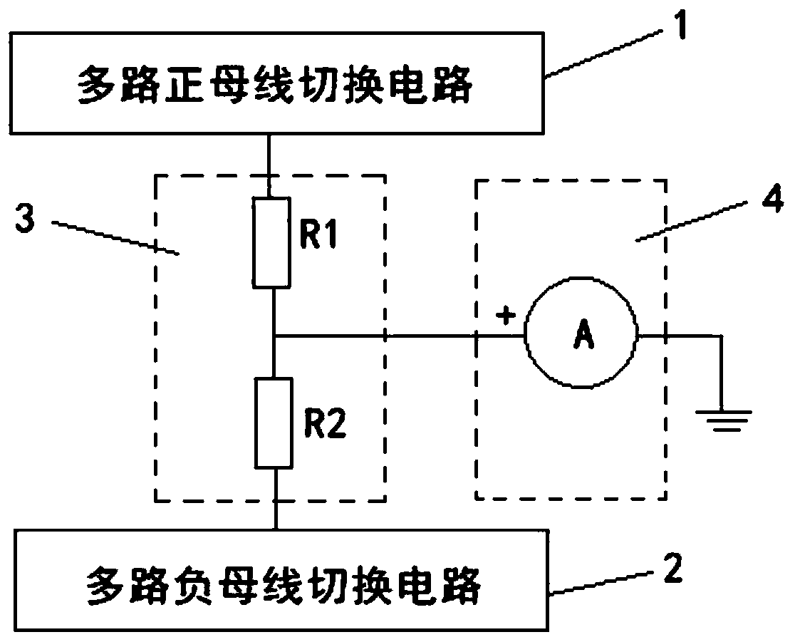
[0040] See figure 1 , The balanced multi-channel bus insulation monitoring device provided by the present invention includes: a multi-channel bus switching circuit, a balanced circuit 3, and an insulation monitoring circuit 4. The multi-channel bus switching circuit is divided into a multi-channel positive bus switching circuit 1 and a multi-channel negative bus. Switching circuit 2. The balance circuit 3 connects the output terminal of the multi-channel positive bus switching circuit 1 and the output terminal of the multi-channel negative bus switching circuit 2, and divides the positive and negative ends of the measured bus. The insulati...


PUM


Abstract

The invention discloses a balanced multi-path bus insulation monitoring device, thereby solving a problem that the existing insulation monitoring device can only realize separate measurement of positive bus insulation resistance to ground and negative bus insulation resistance to ground. A balance circuit is arranged between the output terminals of multiple positive bus switching circuits and theoutput terminals of multiple negative bus switching circuits to perform voltage division on the positive terminal and the negative terminal of a measured bus; and an insulation monitoring circuit is arranged between the output terminal of the balance circuit and a ground wire and monitors the insulation condition between the positive terminal of the measured bus and the ground wire and the insulation condition between the negative terminal of the measured bus and the ground wire at the same time. Repeated configuration of monitoring equipment is avoided, the cost is low, and implementation isconvenient.

Description

Technical field [0001] The invention belongs to the design field of aerospace measurement, launch and control equipment, and in particular relates to a balanced multi-channel bus insulation monitoring device, which is used in a system with multiple buses and the bus and the ground must be isolated. Background technique [0002] The aerospace measurement, launch and control equipment system is relatively large, and multiple power supply buses are configured for different electrical systems to prevent mutual interference between different systems. At the same time, it is required that the different power supply buses and the ground wire should be isolated to reduce the risk of the system sneak path. [0003] Traditional test methods are generally realized by separately collecting the leakage current between the positive, negative and ground of each bus, which is not only costly, but also has the potential connection risk of connecting each bus through two monitoring devices. [0004] ...

Claims


Application Information

Patent Timeline
Patent Type & Authority Applications(China)
IPC IPC(8): G01R27/02G01R31/52G01R31/58
CPCG01R27/025
Inventor 朱奕赵阳潘晓明徐昕顾莉军平佳伟
Owner SHANGHAI AEROSPACE COMP TECH INST
Learn More