Speed governing autodyne phase modulation intelligent control method for pumping unit

An intelligent control and pumping unit technology, which is applied to control multiple AC motors, earthwork drilling and production, and production fluids, can solve problems such as production reduction, damage to oil well equipment and power grid equipment, and labor.

Inactive Publication Date: 2013-06-19
SHAANXI ZHONGXINLIAN ENERGY SAVING NEW TECHDEV
View PDF0 Cites 1 Cited by
  • Summary
  • Abstract
  • Description
  • Claims
  • Application Information

AI Technical Summary

Problems solved by technology

[0002] At present, in my country's onshore oil exploration and production industry, except for self-injection oil wells, other oil wells must use various types of motors to provide power to extract crude oil, and a considerable part of the oil wells have an oil quality of 65, 65, and heavy oil areas are poor oil wells. It is necessa

Method used


Image

  • Speed governing autodyne phase modulation intelligent control method for pumping unit

Examples


Embodiment Construction

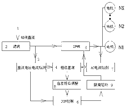
[0010] Such as figure 1 As shown, the intelligent control method for speed regulation, self-difference and phase modulation for pumping units includes at least filter circuit 2, DC voltage and current detection circuit 3, phase reference circuit 4, self-difference phase adjustment circuit 5, DSP control circuit 6, AC current detection circuit Circuit 7 and SPWM circuit 8, bus DC 1 is divided into two circuits after passing filter circuit 2, and one circuit is divided into distributed motors N1, N2, N3, N after passing through SPWM circuit 8 X Electric connection; the other is to the DC voltage and current detection circuit 3, and the DC voltage and current detection circuit 3 is divided into two circuits after processing, one to the phase reference circuit 4, and the other to the DSP control circuit 6; the phase reference circuit 4 is connected to the AC current on the one hand The detection circuit 7 is electrically connected to receive the AC current signal of the motor driv...


PUM


Abstract

The invention relates to a pumping unit controller, in particular to a speed governing autodyne phase modulation intelligent control method for a pumping unit. According to the pumping unit, a three-phase asynchronous motor, a multi-level variable speed motor and a permanent-magnet synchronous motor are used as motive power.

Description

technical field [0001] The invention relates to a controller for a pumping unit, in particular to an intelligent control method for speed regulation, self-difference and phase modulation for the pumping unit. The pumping unit is powered by three-phase asynchronous motor, multi-stage variable speed motor and permanent magnet synchronous motor. Background technique [0002] At present, in my country's onshore oil exploration and production industry, except for self-injection oil wells, other oil wells must use various types of motors to provide power to extract crude oil, and a considerable part of the oil wells have an oil quality of 65, 65, and heavy oil areas are poor oil wells. It is necessary to timely adjust the stroke times of the pumping unit. There are roughly three traditional methods: one is to use a multi-speed motor; the other is to replace the pulley, which is time-consuming, laborious and reduces production; The power grid is seriously disturbed, directly endange...

Claims


Application Information

Patent Timeline
IPC IPC(8): H02P5/74E21B43/00
Inventor 陈曦
Owner SHAANXI ZHONGXINLIAN ENERGY SAVING NEW TECHDEV
Why Eureka
Try Eureka