
An adjustable support for a tower crane

A tower crane, adjustable technology, applied in the field of brackets, can solve problems such as deterioration of stress conditions, difficult operation of the workshop, misplaced collisions, etc., to achieve the effect of avoiding deterioration of conditions, improving practicability, and moving smoothly

Active Publication Date: 2021-12-07
上海紫洵建设机械设备有限公司
View PDF5 Cites 0 Cited by
  • Summary
  • Abstract
  • Description
  • Claims
  • Application Information

AI Technical Summary

Problems solved by technology

[0002] In the prior art, the integral anti-backbracket is used, which is connected to the A-frame through a pin shaft. This connection will cause the integral anti-backbracket to be unable to adjust and move along the direction of the A-frame, resulting in the integral anti-backbracket After the back tilt bracket is installed, there is a misalignment between it and the boom, so that it cannot effectively impact the anti-collision main chord of the root joint of the boom, forming a misalignment collision, and the stress condition deteriorates
[0003] In order to solve this problem in the prior art, it is necessary for the workshop to weld the A-frame, the integral anti-tilt support and the jib root joint together. In addition, the height of the A-frame of some types of tower cranes exceeds the operating height of the workshop. It will lead to difficult operation in the workshop. Even if it is assembled and welded, there is still the problem that the integral anti-backbracket cannot be interchanged, and it is not convenient for customers to replace the integral anti-backbracket after it is damaged.

Method used


Image

  • An adjustable support for a tower crane
  • An adjustable support for a tower crane
  • An adjustable support for a tower crane

Examples


Embodiment 1

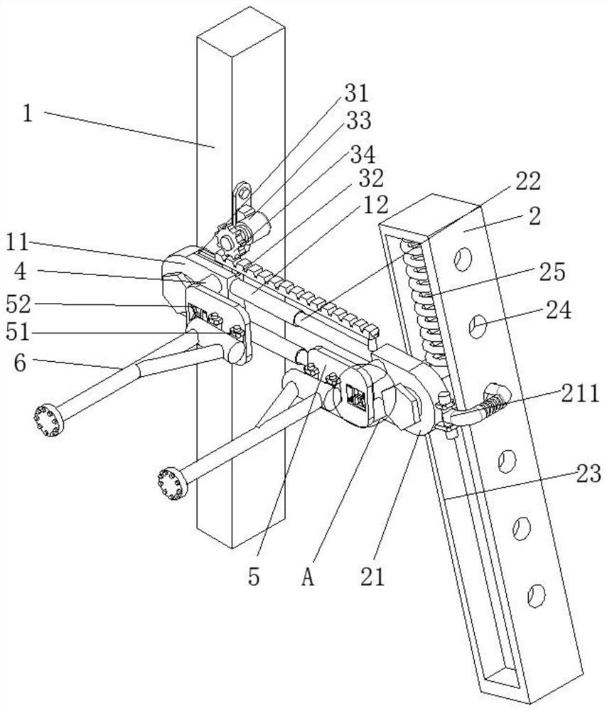
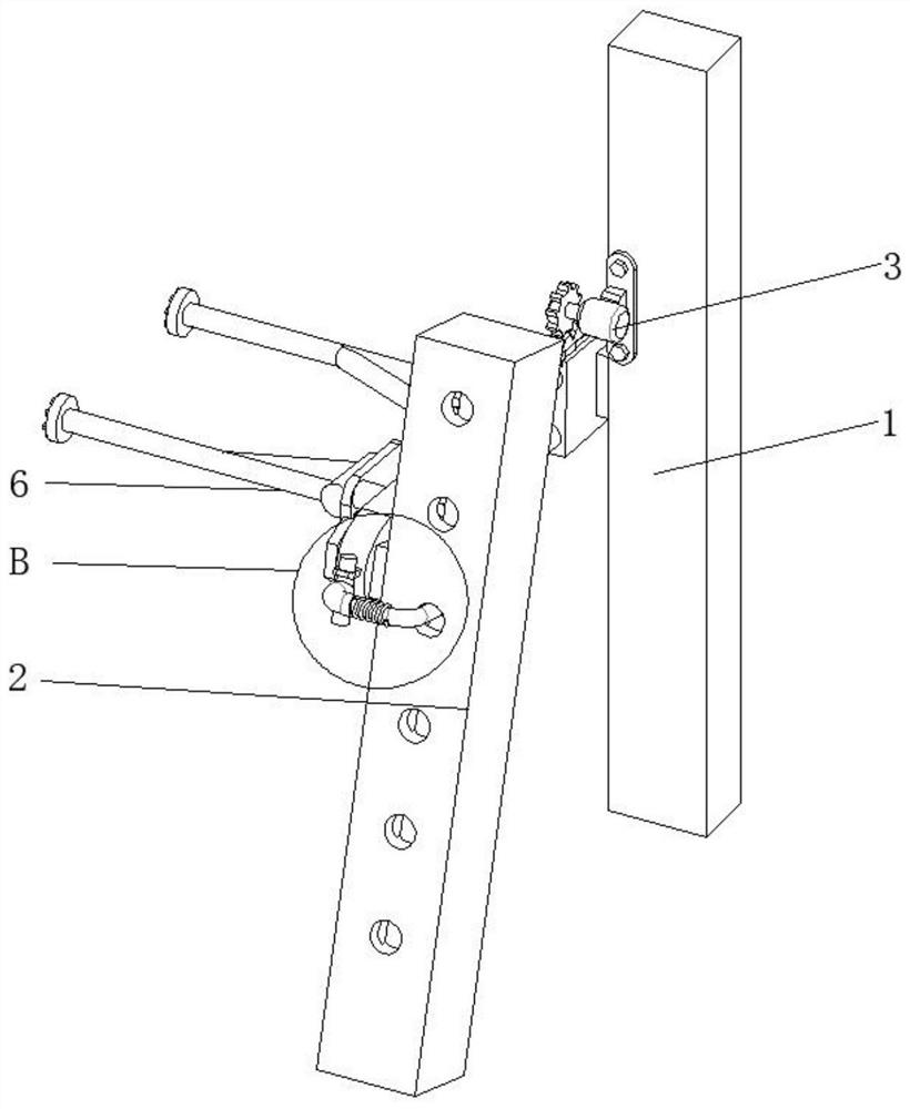
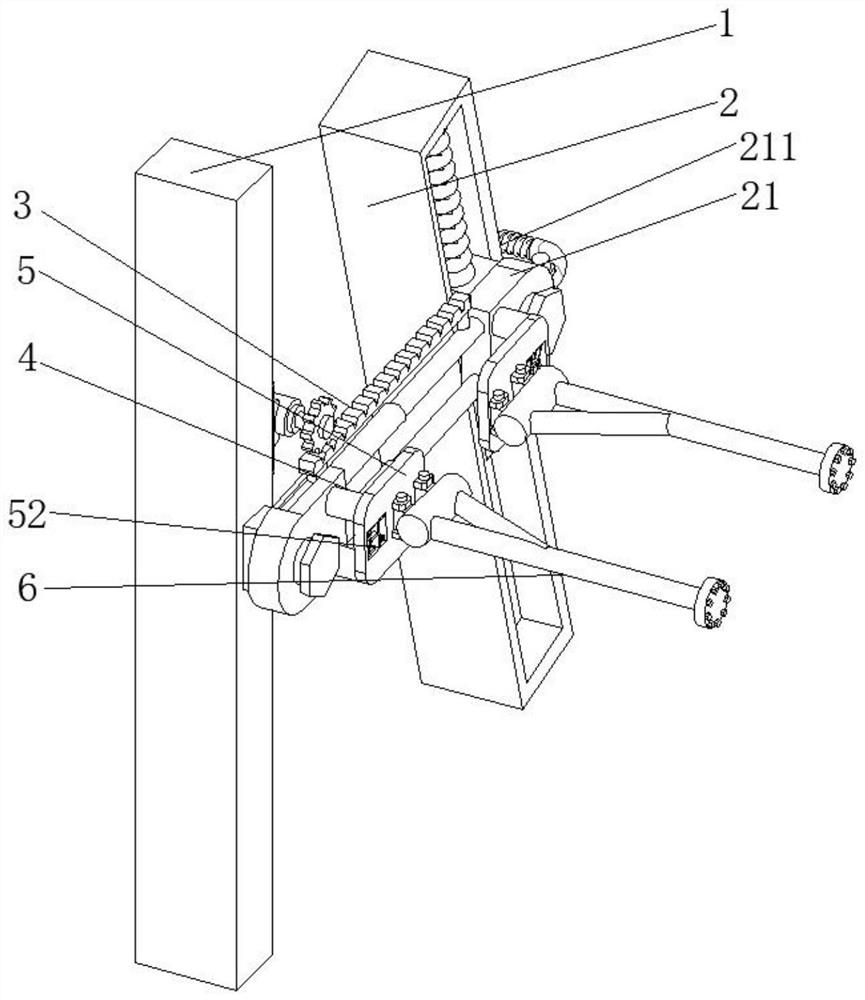
[0023] Example 1, such as Figure 1-5 As shown, the present invention provides an adjustable bracket for a tower crane, comprising a No. 1 A-frame 1 and a No. 2 A-frame 2. The outer surface of the No. 1 A-frame 1 is connected with a No. A limit groove 23 is provided on the side wall of the outer surface of the No. A frame 2, and the inner wall of the limit groove 23 is slidably connected with the second block 21, and the tops of the first block 11 and the second block 21 are fixedly installed with a mounting column 4 , the ends of the two mounting columns 4 away from the No. 1 block 11 and the No. 2 block 21 are fixedly mounted with a mounting plate 5, and the top and both sides of the mounting plate 5 are fixedly mounted with a No. 2 rotating shaft 51, and the mounting plate 5 passes through the No. 2 rotating shaft 51 Rotationally connected with bracket 6, one side wall of No. 1 A-frame 1 is fixedly equipped with adjusting structure 3, and the outer surfaces of No. 2 A-frame...


PUM


Abstract

The invention provides an adjustable bracket for a tower crane, which relates to the technical field of brackets and includes a No. 1 A-frame and a No. 2 A-frame. The outer surface of the No. 1 A-frame is connected to a No. There is a limit groove on one side wall of the outer surface of the frame, the inner wall of the limit groove is slidingly connected with the second block, and the tops of the first block and the second block are fixedly installed with mounting columns, and the two mounting columns are respectively far away from the first block And one end of the No. 2 block is fixedly installed with a mounting plate. In the present invention, the rebound force of the limit spring makes the movement more stable when the No. 2 block drives the bracket to fine-tune. Since the fixed positions of the No. 1 A-frame and the No. 2 A-frame and the bracket are adjustable, they can be moved and adjustment to adapt to the position of the root section of the arm, so that the two can collide correctly, and effectively impact the anti-collision main chord of the root section of the arm, avoiding the occurrence of dislocation collisions and deterioration of working conditions caused by force, and improving the support practicality.

Description

technical field [0001] The invention relates to the technical field of supports, in particular to an adjustable support for a tower crane. Background technique [0002] In the prior art, the integral anti-backbracket is used, which is connected to the A-frame through a pin shaft. This connection will cause the integral anti-backbracket to be unable to adjust and move along the direction of the A-frame, resulting in the integral anti-backbracket After the back tilt bracket is installed, there is a misalignment between it and the boom, so that it cannot effectively impact the anti-collision main chord of the root joint of the boom, forming a misalignment collision, and the stress condition deteriorates. [0003] In order to solve this problem in the prior art, it is necessary for the workshop to weld the A-frame, the integral anti-tilt support and the jib root joint together. In addition, the height of the A-frame of some types of tower cranes exceeds the operating height of t...

Claims


Application Information

Patent Timeline
Patent Type & Authority Patents(China)
IPC IPC(8): B66C23/62B66C23/64B66C23/78
CPCB66C23/62B66C23/64B66C23/78B66C2700/03
Inventor 李杰
Owner 上海紫洵建设机械设备有限公司
Learn More