Method and device for visualizing static relationship network relationship edge

A relational network and relational technology, applied in other database browsing/visualization, program control devices, other database retrieval, etc., can solve the problems of poor visual effect and increased graphic load, achieve intuitive perception, reduce graphic load, The effect of enhancing the sense of direction

Pending Publication Date: 2020-06-23
PLA STRATEGIC SUPPORT FORCE INFORMATION ENG UNIV PLA SSF IEU
View PDF5 Cites 0 Cited by
  • Summary
  • Abstract
  • Description
  • Claims
  • Application Information

AI Technical Summary

Problems solved by technology

[0003] The purpose of the present invention is to provide a method and device for visualizing the relationship edges of a static relationship network, which are used to solve the problems of increased graphics load and poor visual effects in the relationship edge visualization method in the prior art

Method used


Image

  • Method and device for visualizing static relationship network relationship edge
  • Method and device for visualizing static relationship network relationship edge
  • Method and device for visualizing static relationship network relationship edge

Examples


Embodiment Construction

[0030] The specific embodiments of the present invention will be further described below in conjunction with the accompanying drawings.

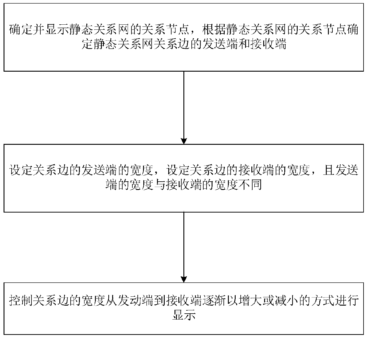
[0031] The present invention proposes a method for visualizing relational edges of a static relational network, such as figure 2 shown, including the following steps:

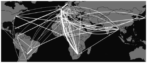
[0032] 1) Determine and display the relationship nodes of the static relationship network, and determine the sender and receiver of the relationship edge of the static relationship network according to the relationship nodes of the static relationship network;

[0033] 2) Set the width of the sending end of the relationship edge, set the width of the receiving end of the relationship edge, and the width of the sending end is different from the width of the receiving end;

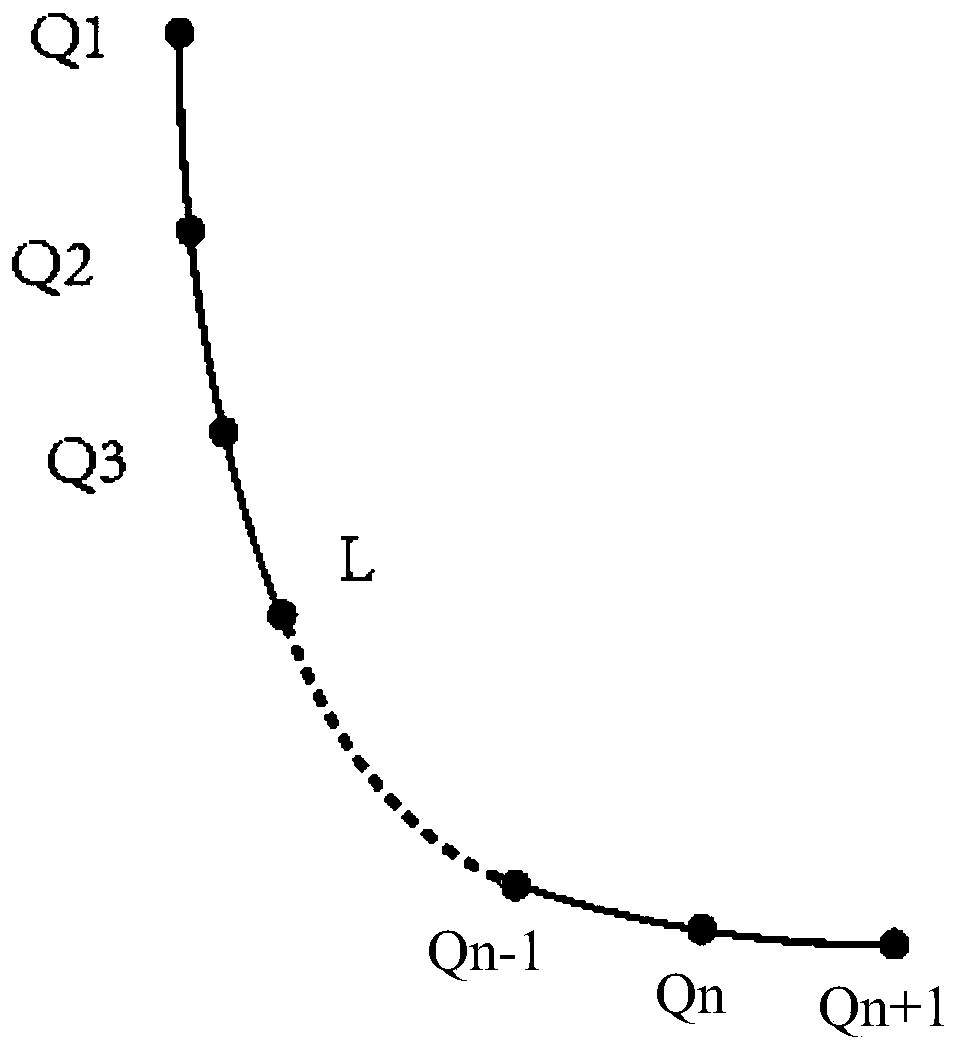
[0034] 3) Control the width of the relationship edge to gradually increase or decrease from the sending end to the receiving end.

[0035] The present invention optimizes the visual effect of the directi...


PUM


Abstract

The invention relates to a visualization method and device for a static relationship network relationship edge, and belongs to the field of relationship network visualization. The method includes: determining a sending end and a receiving end of a static relationship network relationship edge according to the relationship node of the static relationship network, the width of the sending end beinggreater than the width of the receiving end, dividing the relationship edge into at least two sections, and when the relationship edge is divided into two sections, the width of one section of the relationship edge being the width of the receiving end and the width of the other section of the relationship edge being the width of the sending end; when the relation edge is divided into more than three sections; starting from the relation edge of the section where the receiving end is located to the relation edge of the section where the sending end is located, the width is set for the relation edge of each section in sequence from small to large, the width of the relation edge of the section where the receiving end is located is the smallest and is the width of the receiving end, and the width of the relation edge of the section where the sending end is located is the largest and is the width of the sending end; and displaying all relationship nodes of the static relationship network, and displaying all relationship edges of the static relationship network in a width gradual change mode.

Description

technical field [0001] The invention belongs to the field of relationship network visualization, and in particular relates to a method and device for visualizing relationship edges of a static relationship network. Background technique [0002] At present, static relationship networks (including various social relationship networks, co-author relationship networks, and other relationship networks at a certain point in time regardless of their time changes) are often displayed based on a graph model when they are visualized, that is, the relationship nodes are abstracted into points. The relationship between relationship nodes is abstracted as edges, and the abstract points and abstract edges are laid out on the display interface to complete the display of the relationship network. For a static relational network, the direction of the relation is an important content that needs to be expressed. In the prior art, the direction display in the static relationship network visual...

Claims


Application Information

Patent Timeline
Patent Type & Authority Applications(China)
IPC IPC(8): G06F9/451G06F16/901G06F16/904
CPCG06F9/451G06F16/9024G06F16/904
Inventor 华一新文娜江南张江水陈敏颉陈云海
Owner PLA STRATEGIC SUPPORT FORCE INFORMATION ENG UNIV PLA SSF IEU
Why Eureka
Try Eureka