A CNC lathe with automatic loading and unloading structure

An automatic loading and unloading, CNC lathe technology, applied in the field of CNC lathes, can solve the problems of unsuitable shaft parts, unsuitable for promotion and use, unable to meet the production of small and medium batches of shaft parts of multiple specifications, etc., to achieve easy replacement and avoid failure. The effect of timely processing

Active Publication Date: 2021-11-09
SHANGHAI WORKPOWER TELECOM TECH +1
View PDF9 Cites 2 Cited by
  • Summary
  • Abstract
  • Description
  • Claims
  • Application Information

AI Technical Summary

Problems solved by technology

[0002] In lathe CNC machining, in order to save human resources and reduce labor intensity, people have designed a variety of automatic loading and unloading devices for lathes. At present, most of them are used for automatic loading and unloading of round lathe bars. Most of these parts are formed at one time. But it is not applicable to shaft parts for secondary processing
There are also some application cases for the automatic loading and unloading device of the lathe for secondary processing, such as patent No. CN201510132876.6 and CN201821087191. Both adopt the direct push type of vibrating plate feeding to feed the jaws of the lathe. The direct pushing methods of the two devices are different. The vibrating plate is effective for a single product, but it is not effective for products with multiple specifications, which has great limitations. , not suitable for popularization and use, and unable to meet the production of small and medium batches and multi-standard shaft parts

Method used


Image

  • A CNC lathe with automatic loading and unloading structure
  • A CNC lathe with automatic loading and unloading structure
  • A CNC lathe with automatic loading and unloading structure

Examples


Embodiment Construction

[0027] In order to make the object, technical solution and advantages of the present invention more clear, the present invention will be further described in detail below in conjunction with the examples. It should be understood that the specific embodiments described here are only used to explain the present invention, not to limit the present invention.

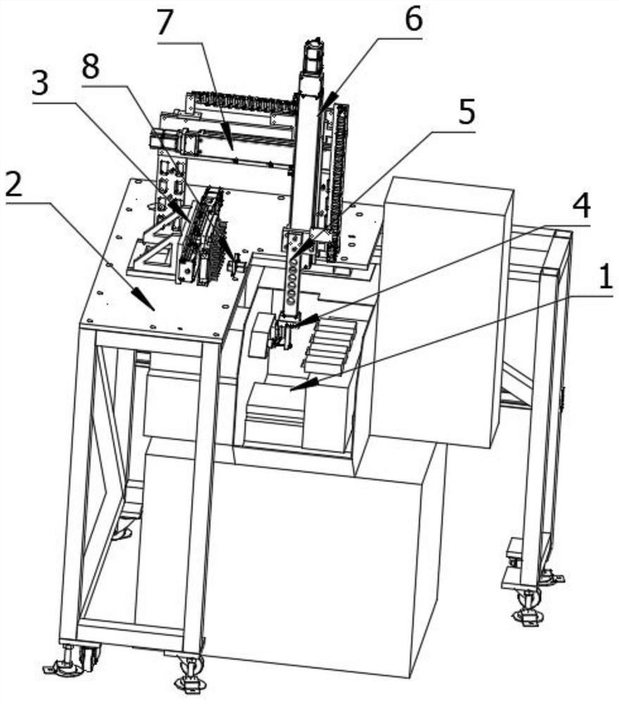
[0028] A numerical control lathe with an automatic loading and unloading structure, comprising a lathe 1; lathe jaws 11 are installed inside the lathe 1; a support platform 2 is installed on the top of the lathe 1, and a rod is installed on the surface of the support platform 2 Material storage mechanism 3, Y-axis motion assembly 7 and material receiving mechanism 8; The X-axis direction of the bar stock storage mechanism 3 is provided with the Y-axis motion assembly 7, and the Y-axis direction of the bar stock storage mechanism 3 is provided with The receiving mechanism 8; the receiving mechanism 8 is located on the side o...


PUM


Abstract

A CNC lathe with an automatic loading and unloading structure, comprising a lathe; lathe clamps are installed inside the lathe; a support platform is installed on the top of the lathe, and a bar stock storage mechanism, a Y-axis, etc. are installed on the surface of the support platform Motion assembly and material receiving mechanism; the X-axis direction of the bar storage mechanism is provided with the Y-axis movement assembly, the Y-axis direction of the bar storage mechanism is provided with the material receiving mechanism, and the material receiving mechanism is set On the side of the bar stock storage mechanism close to the lathe jaw; the Y-axis motion assembly is slidably connected with a Z-axis motion assembly; the present invention realizes lathe shaft parts by setting up an automatic loading and unloading mechanism above the lathe. The automatic loading and unloading of the parts, the parts grabbing mechanism is designed to adjust the jaws and the fixed plate to adapt to the processing of shaft parts with different lengths and diameters. At the same time, the setting of the spring is to protect the parts from being crushed during the loading and unloading project.

Description

technical field [0001] The invention belongs to the technical field of lathe numerical control processing, in particular to a numerical control lathe with an automatic loading and unloading structure. Background technique [0002] In lathe CNC machining, in order to save human resources and reduce labor intensity, people have designed a variety of automatic loading and unloading devices for lathes. At present, most of them are used for automatic loading and unloading of round lathe bars. Most of these parts are formed at one time. However, it is not applicable to shaft parts for secondary processing. There are also some application cases for the automatic loading and unloading device of the lathe for secondary processing, such as patent No. CN201510132876.6 and CN201821087191. Both adopt the direct push type of vibrating plate feeding to feed the jaws of the lathe. The direct pushing methods of the two devices are different. The vibrating plate is effective for a single pro...

Claims


Application Information

Patent Timeline
Patent Type & Authority Patents(China)
IPC IPC(8): B23B15/00B23Q7/04B23Q17/00
CPCB23Q7/04B23Q17/00
Inventor 高伟亚云轩张集谭元英刘林琳
Owner SHANGHAI WORKPOWER TELECOM TECH
Why Eureka
Try Eureka