Roller sand blasting equipment

A kind of sandblasting equipment and sandblasting technology, which is applied in the field of rolls, can solve the problems of poor practicability and uneven surface treatment of workpieces, and achieve the effect of improving practicability and uniform sandblasting treatment

Inactive Publication Date: 2020-06-26
辽宁兆金重型装备制造有限公司
View PDF9 Cites 1 Cited by
  • Summary
  • Abstract
  • Description
  • Claims
  • Application Information

AI Technical Summary

Problems solved by technology

[0002] The sand blasting process is to use compressed air as the power to form a high-speed jet beam, and spray the spray material to the surface of the workpiece to be treated at a high speed, so that the appearance of the outer surface of the workpiece changes. Due to the impact and cutting effect of the abrasive on the surface of the workpiece, the surface of the workpiece is obtained. A certain degree of cleanliness and different roughness improve the mechanical properties of the surface of the workpiece. Most of the existing roll blasting equipment requires manual hand-held sandblasting guns to blast the rolls. Manual hand-holding results in insufficient surface treatment of the blasted workpiece. Uniform, less practical

Method used


Image

  • Roller sand blasting equipment
  • Roller sand blasting equipment
  • Roller sand blasting equipment

Examples


Embodiment Construction

[0017] The specific embodiments of the present invention will be described in further detail below with reference to the accompanying drawings and embodiments. The following examples are intended to illustrate the present invention, but not to limit the scope of the present invention.

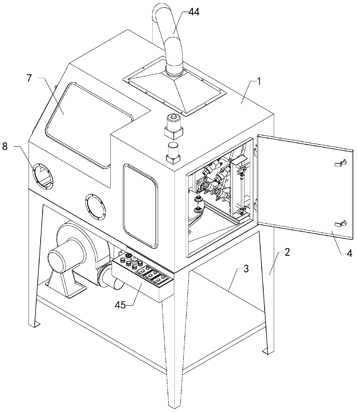
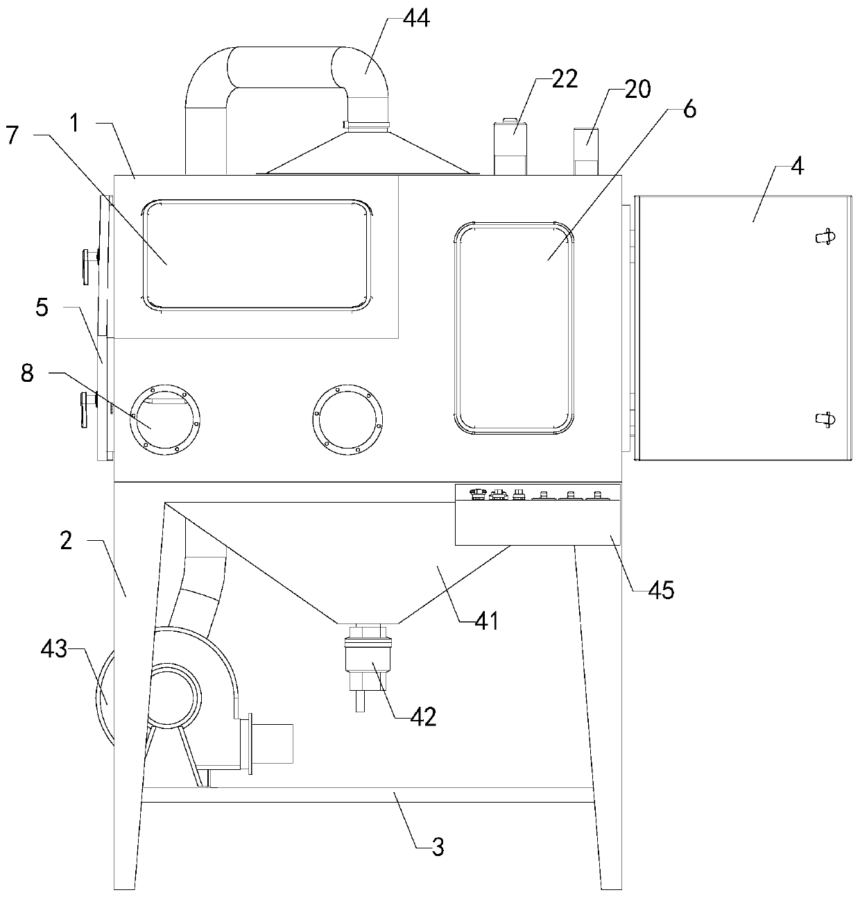
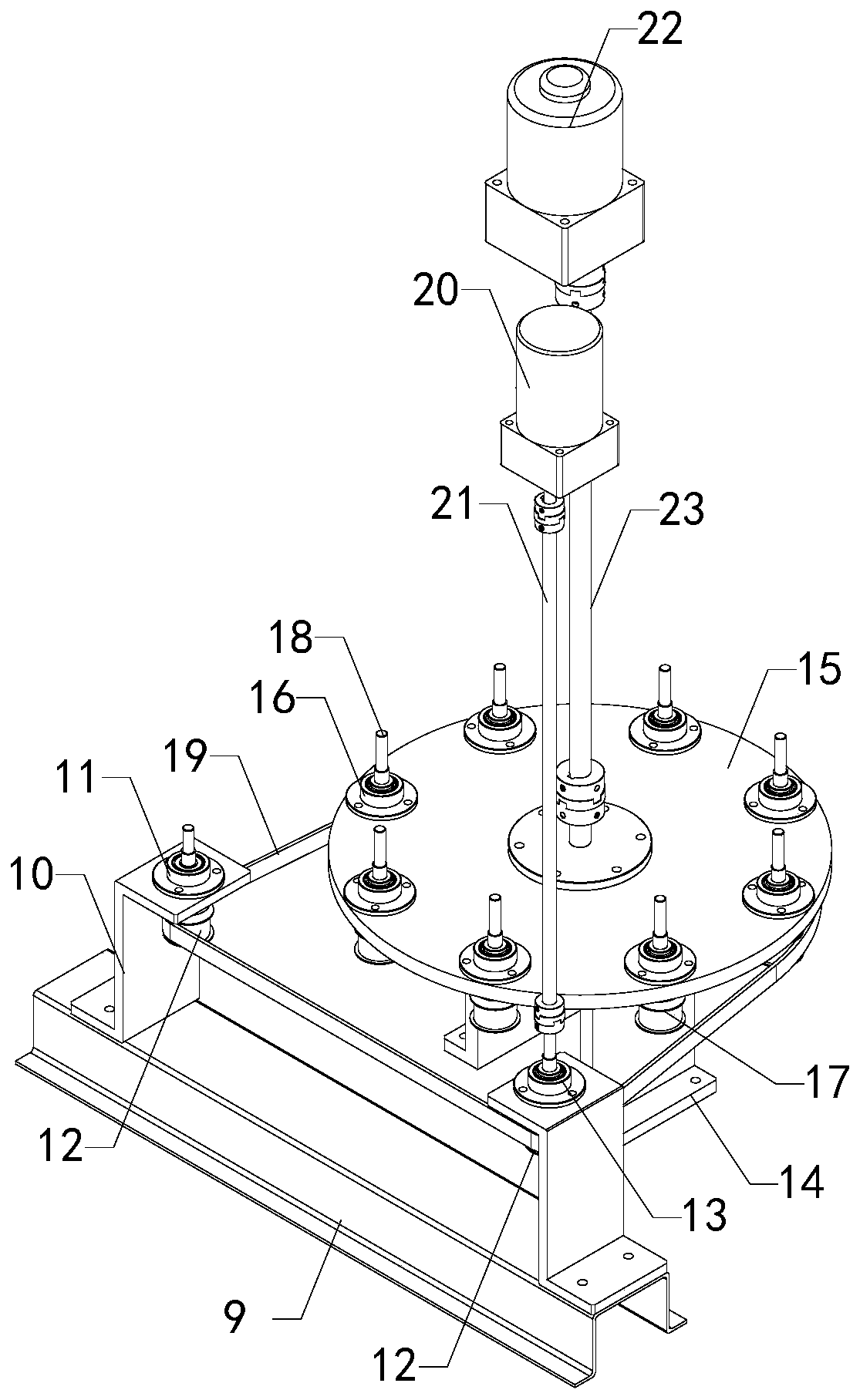
[0018] like Figure 1 to Figure 4 As shown, a roller sandblasting equipment of the present invention includes a sandblasting box 1, a first sealing door 4, a first base 9, two sets of mounting frames 10, a first bearing seat 11, and two sets of first pulleys 12. , second bearing seat 13, second base 14, turntable 15, multiple groups of third bearing seats 16, multiple groups of second pulleys 17, transmission belt 19, first motor 20, first connecting shaft 21, second motor 22 , the second connecting shaft 23 and the spraying device, the interior of the sandblasting box 1 is provided with a chamber, the bottom end of the sandblasting box 1 is provided with four groups of support legs 2, the bot...


PUM


Abstract

The invention relates to the technical field of rollers, in particular to roller sand blasting equipment. The roller sand blasting equipment enables sand blasting treatment on the surface of a rollerto be more uniform and improves practicability. The roller sand blasting equipment comprises a sand blasting box, a first sealing door, a first base, two sets of mounting frames, a first bearing seat,two sets of first belt wheels, a second bearing seat, a second base, a rotary disc, a plurality of sets of third bearing seats, a plurality of sets of second belt wheels, a transmission belt, a firstmotor, a first connecting shaft, a second motor, a second connecting shaft and a spraying device. A cavity is formed inside the sand blasting box, four sets of supporting legs are arranged at the bottom end of the sand blasting box, a bottom plate is arranged at the bottoms of the four sets of supporting legs, a first glass window capable of observing the interior of the cavity of the sand blasting box is arranged on the right portion of the front end of the sand blasting box, and an opening communicating with the cavity of the sand blasting box is formed in the right end of the sand blastingbox; and the rear end of the first sealing door is rotationally and vertically installed at the opening of the right end of the sand blasting box, the first base is fixedly installed at the bottom end of the cavity of the sand blasting box, and the two sets of mounting frames are symmetrically installed at the top end of the first base.

Description

technical field [0001] The invention relates to the technical field of rolls, in particular to a roll sandblasting device. Background technique [0002] The sandblasting process uses compressed air as the power to form a high-speed jet beam, and sprays the material and other high-speed jets to the surface of the workpiece to be treated, so that the appearance of the outer surface of the workpiece changes. A certain degree of cleanliness and different roughness can improve the mechanical properties of the workpiece surface. Most of the existing roller sandblasting equipment requires manual hand-held sandblasting guns to blast the rollers. Manual hand-held results in insufficient surface treatment of the sandblasted workpiece. Uniform, less practical. SUMMARY OF THE INVENTION [0003] In order to solve the above-mentioned technical problems, the present invention provides a sandblasting equipment for the rolls, which makes the sandblasting treatment on the surface of the ro...

Claims


Application Information

Patent Timeline
Patent Type & Authority Applications(China)
IPC IPC(8): B24C1/06B24C3/22B24C9/00B24C5/02
CPCB24C1/06B24C3/22B24C5/02B24C9/00B24C9/003B24C9/006
Inventor 吕永生
Owner 辽宁兆金重型装备制造有限公司
Why Eureka
Try Eureka