Ornament prototype surface sandblasting equipment

A surface sandblasting and processing equipment technology, applied in the field of sandblasting, can solve the problems of sandblasting, drop, poor uniformity, etc., to achieve the effect of expanding the support range, improving sandblasting efficiency, and improving stability

Inactive Publication Date: 2020-02-14
义乌市傅宝仙饰品有限公司
View PDF0 Cites 1 Cited by
  • Summary
  • Abstract
  • Description
  • Claims
  • Application Information

AI Technical Summary

Problems solved by technology

[0003] In the sandblasting process of the existing ring-shaped jewelry through the sandblasting machine, the sandblasting method is usually carried out by holding the ring-shaped jewelry workpiece. The sandblasting machine can neither fix the jewelry nor perform detailed sandblasting on the part according to actual needs. As a result, the uniformity of jewelry sandblasting is poor, and the effect of sandblasting mainly depends on the actual experience of workers, which affects the quality and efficiency of sandblasting. At the same time, jewelry sandblasting usually uses special materials, and the recycling of sandblasting can save processing costs. In some sandblasting machines, the sandblasting will fall on the bottom of the sandblasting chamber, which is inconvenient to clean, resulting in a low recovery rate of sandblasting, and when the jewelry falls, it is very likely to be sucked by the dust suction mechanism and cause damage to the jewelry

Method used


Image

  • Ornament prototype surface sandblasting equipment
  • Ornament prototype surface sandblasting equipment
  • Ornament prototype surface sandblasting equipment

Examples


Embodiment 1

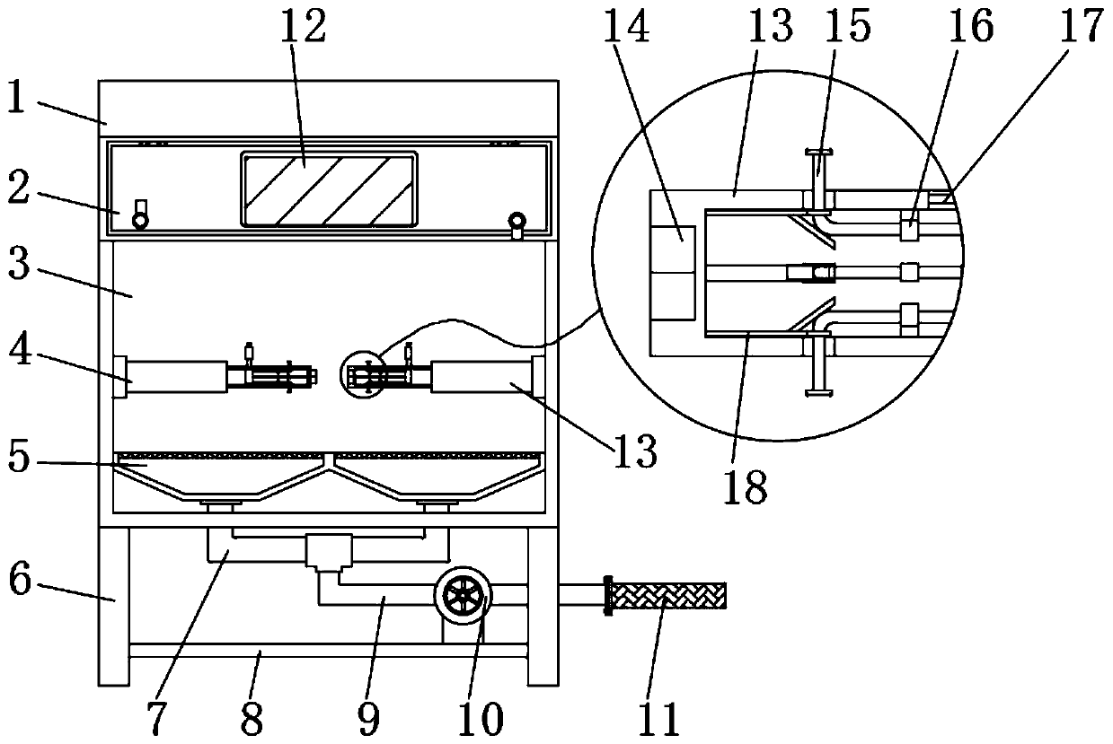
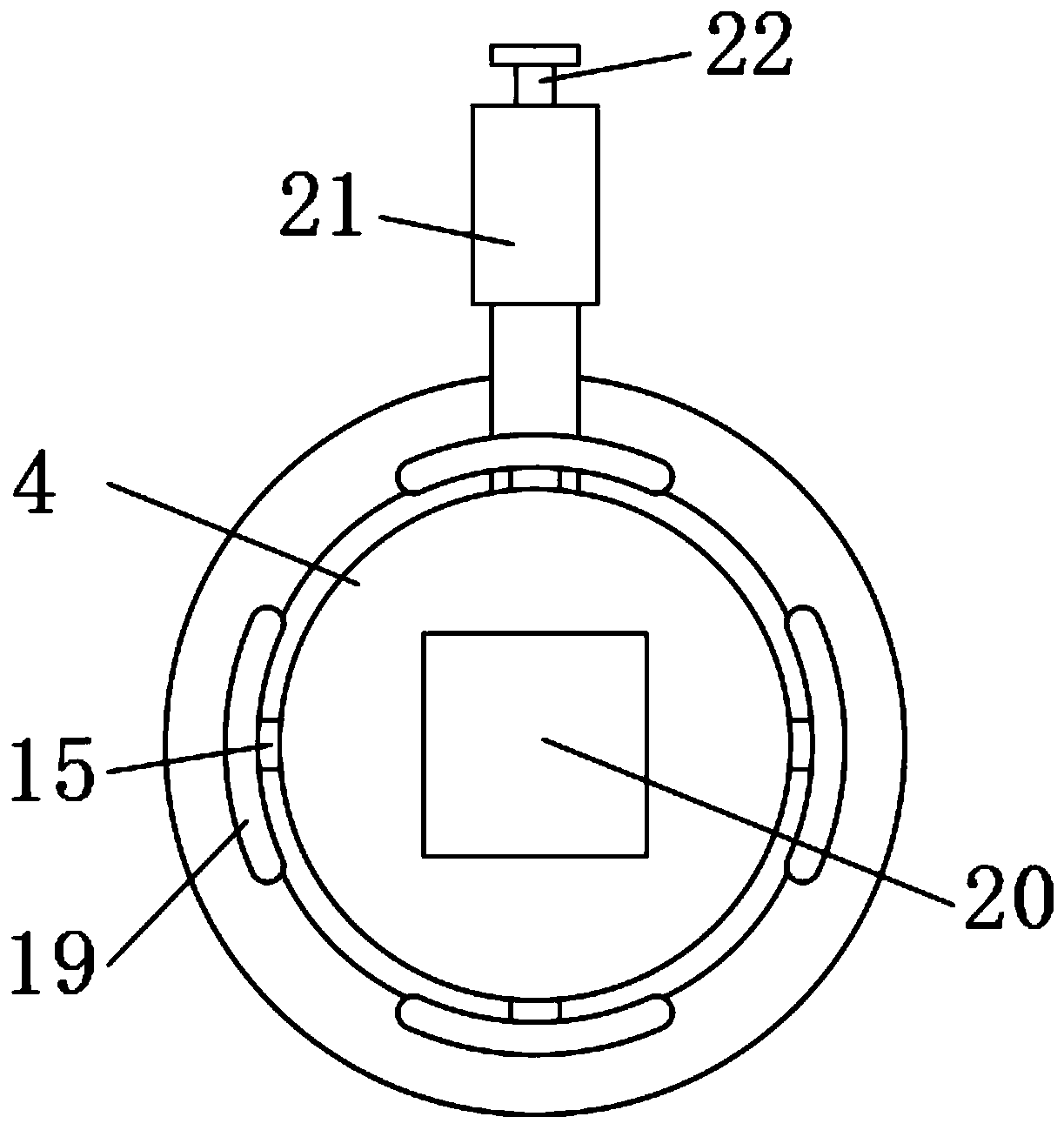
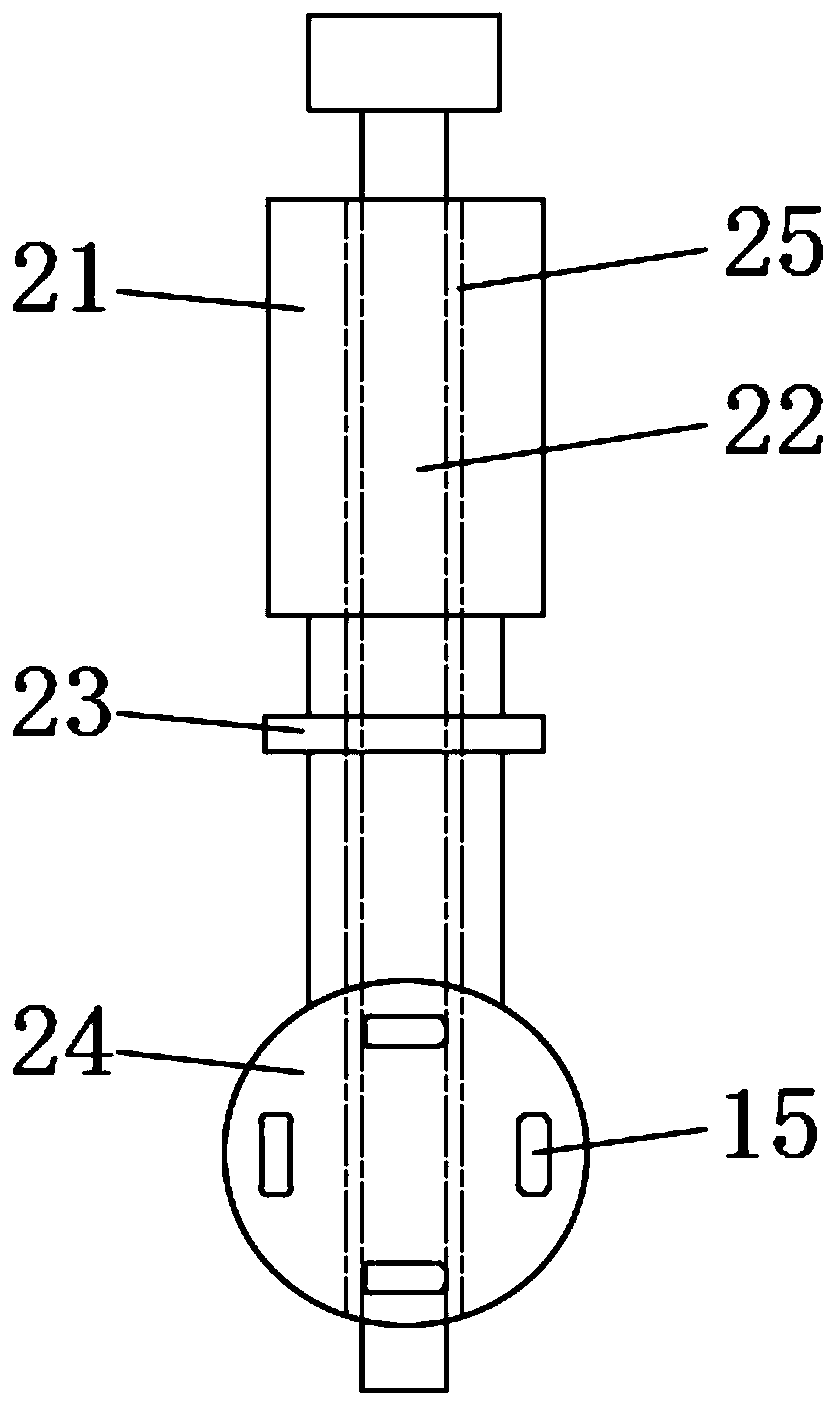
[0029] Embodiment one, with reference to figure 1 , figure 2 , image 3 and Figure 5, a kind of sandblasting treatment equipment for the prototype of jewelry, including a sandblasting machine 1, a sandblasting chamber 3 is opened inside the sandblasting machine 1, and the two sides of the inner wall of the sandblasting chamber 3 are welded with a first telescopic sleeve rod 4 and a second Two telescopic sleeve rods 13, the top surface of the first telescopic sleeve rod 4 and the second telescopic sleeve rod 13 one ends are all provided with chute 17, and the inside of chute 17 is connected with adjusting handle 21 by sliding ring 23, and adjusting handle 21 One end of the first telescopic sleeve rod 4 and the second telescopic sleeve rod 13 are welded with a support plate 24, and a plastic strip 15 is fixedly installed on the surface of the support plate 24, and a fixed sleeve 16 is sleeved on the surface of the plastic strip 15. And one side of the plastic strip 15 is lo...

Embodiment 2

[0030] Embodiment two, refer to figure 1 , the top surface of the sandblasting chamber 3 is located below the first telescopic sleeve rod 4 and the second telescopic sleeve rod 13, and two dust collection covers 5 are fixedly installed, and the top surfaces of the two dust collection covers 5 are welded with hollow mesh, The bottom surface of the sandblasting machine 1 is provided with a connecting pipe 7 of U-shaped structure, and both ends of the connecting pipe 7 run through the sandblasting machine 1 and connect with the bottom surfaces of the two dust collection hoods 5, and the middle position of the connecting pipe 7 passes through a tee Connected with dust suction pipe 9, and dust suction fan 10 is installed on the surface of dust suction pipe 9, and one end flange of dust suction pipe 9 is connected with filter bag 11, and the surface of sand blasting machine 1 is equipped with control panel, and the control panel The output end is electrically connected to the dust s...

Embodiment 3

[0031] Embodiment three, refer to figure 1 and Figure 4 , the top surface of the sandblasting machine 1 is hinged to install the outer door 2, and the edge of the inner surface of the outer door 2 is bonded with a sealing strip 26, and the edge of the outer door 2 is symmetrically welded with two bosses 27, And the surfaces of the two bosses 27 are all ring-connected with a rubber sleeve 28, and one end of the rubber sleeve 28 is provided with an abutment block, and the abutment block abuts against the shell of the sandblasting machine 1, and the middle position on the surface of the outer door 2 is opened. There is a visible window 12, when it is necessary to open the outward opening door 2, by rotating the rubber sleeve 28, one end of the rubber sleeve 28 is forced to break away from the state of abutting against the shell of the sandblasting machine 1, thereby facilitating opening the outward opening door 2 for taking or carrying out jewelry. The maintenance of the sandbl...


PUM


Abstract

The invention discloses ornament prototype surface sandblasting equipment which comprises a sandblasting machine, and a sandblasting cavity is arranged in the sandblasting machine. According to the ornament prototype surface sandblasting equipment, a jewelry ring to be subjected to sandblasting is arranged on object loading blocks of a first telescopic sleeve rod and a second telescopic sleeve rodin a sleeve manner, then the first telescopic sleeve rod and the second telescopic sleeve rod are stretched in opposite directions, connecting columns of quadrangular structures and connecting grooves are in butt joint, adjusting handles on the surfaces of the first telescopic sleeve rod and the second telescopic sleeve rod slide to promote supporting discs at the bottom ends of the adjusting handles to push multiple plastic strips to move under the sleeving, connecting and supporting actions of a fixed sleeve, and therefore the plastic strips penetrate through avoiding holes of the first telescopic sleeve rod and the second telescopic sleeve rod and through grooves in a support plate to outwards extend, in cooperation with the guide effect of guide strips, the supporting scope of the object loading blocks of the multiple arc-shaped structures is enlarged, the multiple object loading blocks are promoted to support and carry an inner ring of the jewelry ring to be processed, and the ornament prototype surface sandblasting equipment is suitable for fixing and supporting jewelry rings with different diameters.

Description

technical field [0001] The invention relates to the technical field of sand blasting, in particular to a sand blasting treatment device for the surface of a prototype of an ornament. Background technique [0002] During the production and processing of some handicrafts or jewelry, the surface needs to be sandblasted. Among them, sandblasting is a process of cleaning and roughening the surface of the substrate by the impact of high-speed sand flow. [0003] In the sandblasting process of the existing ring-shaped jewelry through the sandblasting machine, the sandblasting method is usually carried out by holding the ring-shaped jewelry workpiece. The sandblasting machine can neither fix the jewelry nor perform detailed sandblasting on the part according to actual needs. As a result, the uniformity of jewelry sandblasting is poor. The effect of sandblasting mainly depends on the actual experience of workers, which affects the quality and efficiency of sandblasting. At the same t...

Claims


Application Information

Patent Timeline
Patent Type & Authority Applications(China)
IPC IPC(8): B24C3/04B24C9/00
CPCB24C3/04B24C9/00B24C9/003
Inventor 朱永红王起任大龙
Owner 义乌市傅宝仙饰品有限公司
Why Eureka
Try Eureka