Method and apparatus of non-contact tool center point calibration for a mechanical arm, and a mechanical arm system with said calibration function

A technology of tool center point and mechanical arm, applied in the direction of manipulator, program-controlled manipulator, manufacturing tool, etc., can solve the problems of high human influence factors, large error, and reduced utilization rate of equipment

Active Publication Date: 2020-06-26
IND TECH RES INST
View PDF5 Cites 2 Cited by
  • Summary
  • Abstract
  • Description
  • Claims
  • Application Information

AI Technical Summary

Problems solved by technology

However, with the automatic production of robotic arms, the difficulty that needs to be overcome is the problem of mechanical movement errors and corrections.
[0003] The traditional calibration method uses contact calibration. However, the operator controls the robotic arm to touch a sharp point at various angles in the contact calibration, which has the disadvantages of high human influence factors, time-consuming, large errors, and the inability to correct three-dimensional rotation.
What's more, usually when a collision occurs or a workpiece is replaced, it must be recalibrated immediately, and the disadvantage of time-consuming recalibration will further lead to a reduction in the utilization rate of the machine tool

Method used


Image

  • Method and apparatus of non-contact tool center point calibration for a mechanical arm, and a mechanical arm system with said calibration function
  • Method and apparatus of non-contact tool center point calibration for a mechanical arm, and a mechanical arm system with said calibration function
  • Method and apparatus of non-contact tool center point calibration for a mechanical arm, and a mechanical arm system with said calibration function

Examples


Embodiment Construction

[0037] The detailed features and advantages of the present invention are described in detail below in the embodiments, which are sufficient to enable those skilled in the art to understand the technical content of the present invention and implement it accordingly, and according to the contents disclosed in this specification, claims and drawings, any The related objects and advantages of the present invention can be easily understood by those skilled in the art. The following examples further illustrate the concept of the present invention in detail, but do not limit the scope of the present invention in any way.

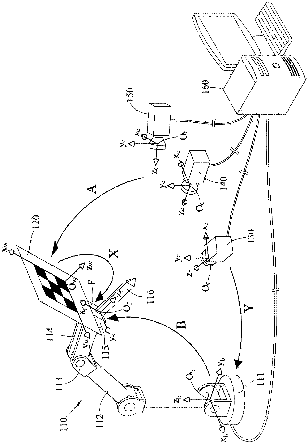
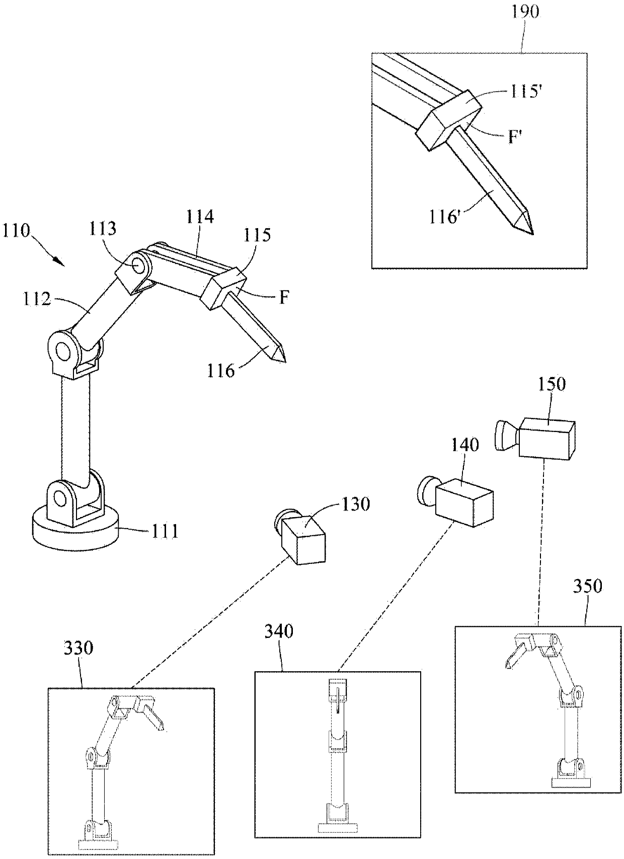
[0038] see figure 1 , which shows a robotic arm 110 for performing the non-contact tool center point (ToolCenter Point, TCP) calibration method of the robotic arm of the present invention. The non-contact tool center point calibration method of the robotic arm of the present invention is not limited to implementation in A mechanical arm with this structure. The r...


PUM


Abstract

This disclosure is related to a non-contact tool center point calibration method for a robot arm, and the method comprises: obtaining a coordinate transformation relationship between a flange surfaceof the robot arm and cameras by a hand-eye calibration algorithm; constructing a space coordinate system by a stereoscopic reconstruction method; actuating a replaceable member fixed with the flange surface to present postures in a union field of view of the cameras sequentially, recording feature coordinates of the replaceable member in the space coordinate system, and recording flange surface coordinates which is under the postures in the space coordinate system; obtaining a transformation relationship between a tool center point and the flange surface; and updating the transformation relationship into a control program of the robot arm. Moreover, the disclosure further discloses a calibration device performing the calibration method and a robot arm system having the calibration function.

Description

technical field [0001] The invention relates to a mechanical arm correction device and its method, and a mechanical arm system with correction function, in particular to a mechanical arm non-contact tool center point correction device and its method. Background technique [0002] Since automation is the trend in recent years in industrial production, many assembly line production processes use a large number of robotic arms to replace human production. However, the difficulty that needs to be overcome with the automated production of robotic arms is the problem of mechanical movement errors and calibration. [0003] The traditional calibration method uses contact calibration. However, the operator controls the robotic arm to touch a sharp point at various angles in the contact calibration, which has the disadvantages of high human influence factors, time-consuming, large errors, and the inability to correct three-dimensional rotation. . What's more, usually when a collisio...

Claims


Application Information

Patent Timeline
Patent Type & Authority Applications(China)
IPC IPC(8): B25J9/16
CPCB25J9/1697B25J9/1602B25J9/1692G05B2219/39008
Inventor 许胜杰杨皓翔黄甦杜彦颐
Owner IND TECH RES INST
Why Eureka
Try Eureka