Foundation pit supporting structure

A technology for supporting structures and foundation pits, which is applied in foundation structure engineering, excavation, construction, etc., can solve the problems of inability to support the foundation pit support structure, poor support stability, and inability to support soil retaining boards, etc., to achieve high reliability , Guaranteed support effect, strong practical effect

Pending Publication Date: 2020-06-26
POWERCHINA CHENGDU ENG
View PDF0 Cites 4 Cited by
  • Summary
  • Abstract
  • Description
  • Claims
  • Application Information

AI Technical Summary

Problems solved by technology

[0003] In order to ensure its stability, the general foundation pit support structure needs to be supported. The support stability of the traditional support structure is poor, and it cannot be adjusted. It cannot support the retaining boards of different heights, so it cannot The foundation pit support structure plays a good supporting role

Method used


Image

  • Foundation pit supporting structure
  • Foundation pit supporting structure
  • Foundation pit supporting structure

Examples


Embodiment 1

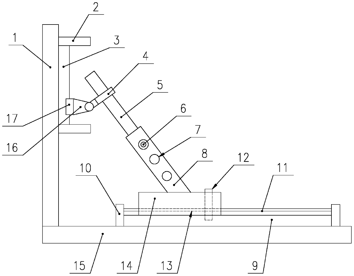
[0034] combine figure 1 with figure 2 As shown, the support structure of the foundation pit includes a soil retaining plate 1 blocked on the side wall of the foundation pit and a horizontal plate 15 arranged at the bottom of the foundation pit. A telescopic support device is arranged on the horizontal plate 15, and the telescopic support rod of the telescopic support device faces The outer wall of the earth retaining plate 1; the outer wall of the earth retaining plate 1 is provided with a first connecting plate 3, and the first connecting plate 3 is provided with a slider 17, which can be detached from parts of different heights on the first connecting plate 3 connection; the slider 17 is hinged with a fixed ring 4, and the fixed ring 4 is set on the telescopic support rod of the telescopic support device;

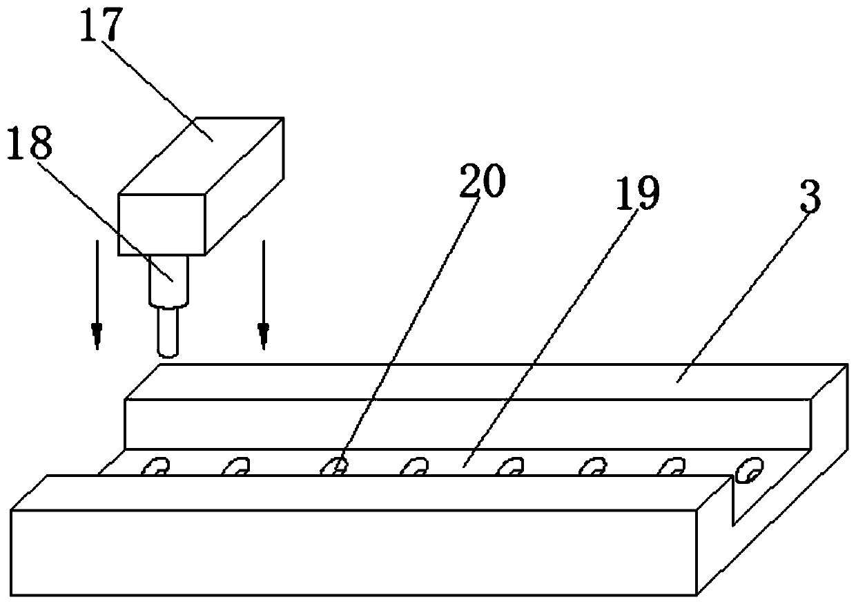
[0035]The outer wall of the first connecting plate 3 is provided with a chute 19, and the chute 19 is provided with at least two spacing holes 20 distributed up and dow...

Embodiment 2

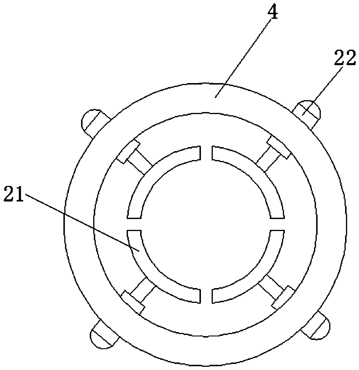
[0041] combine figure 1 with image 3 As shown, the supporting structure of the foundation pit includes a soil retaining plate 1 blocked on the side wall of the foundation pit and a horizontal plate 15 arranged at the bottom of the foundation pit. A telescopic support device is arranged on the horizontal plate 15, and the telescopic support rod of the telescopic support device faces The outer wall of the earth retaining plate 1; the outer wall of the earth retaining plate 1 is provided with a first connecting plate 3, and a slider 17 is arranged on the first connecting plate 3, and the sliding block 17 can be detached from parts of different heights on the first connecting plate 3 connection; the slider 17 is provided with a connection seat 16, the connection seat 16 is hinged with a fixed ring 4, and the fixed ring 4 is set on the telescopic support rod of the telescopic support device;

[0042] The peripheral wall of the fixed ring 4 is provided with a third electric push r...


PUM


Abstract

The invention belongs to the technical field of foundation pit supporting, and particularly discloses a foundation pit supporting structure capable of supporting breast boards with different heights.According to the foundation pit supporting structure, a first connecting plate is arranged on an outer wall of the breast board, a sliding block which can be detachably connected with different heightparts on the first connecting plate is arranged on the first connecting plate, and therefore the height of a supporting point of the breast board can be adjusted by connecting the sliding block to the different height parts; meanwhile, through a telescopic supporting device arranged on a horizontal plate, a telescopic supporting rod of the telescopic supporting device faces the outer wall of thebreast board and is connected in a fixed ring hinged to the sliding block in a sleeved mode, and after the sliding block is connected to a proper supporting point position, the breast board can be effectively supported by adjusting the telescopic amount of the telescopic supporting rod; and the purpose of supporting the breast boards with different heights is achieved.

Description

technical field [0001] The invention belongs to the technical field of foundation pit support, and in particular relates to a foundation pit support structure. Background technique [0002] Foundation pit support is to ensure the safety of the underground structure construction and the surrounding environment of the foundation pit. The support, reinforcement and protection measures are adopted for the side wall of the foundation pit and the surrounding environment; the common support methods mainly include: row pile support, pile Brace, pile anchor, row of pile cantilever, underground diaphragm wall support, ground connection wall plus support, cement retaining wall, soil nail wall, inverted arch wall, undisturbed soil grading, pile, wall plus support system, simple horizontal support , reinforced concrete row piles, etc., the reasonable combination of the above two or more methods can realize foundation pit support. [0003] In order to ensure its stability, the general fo...

Claims


Application Information

Patent Timeline
Patent Type & Authority Applications(China)
IPC IPC(8): E02D17/04
CPCE02D17/04
Inventor 邓子谦徐清袁泉李青春胡金山陈卫东
Owner POWERCHINA CHENGDU ENG
Why Eureka
Try Eureka