
Pressure intensity experiment instrument detection equipment

A technology of experimental instruments and testing equipment, which is applied in the field of pressure experimental instruments and testing equipment, can solve problems such as troublesome operation, and achieve the effects of convenient marking, increasing the tightness of attachment, and simple operation

Inactive Publication Date: 2020-06-26
CHONGQING UNIV OF ARTS & SCI
View PDF0 Cites 3 Cited by
  • Summary
  • Abstract
  • Description
  • Claims
  • Application Information

AI Technical Summary

Problems solved by technology

[0004] The present invention intends to provide a testing device for a pressure experiment instrument to solve the problem in the prior art that after the sealing test is performed, due to a large amount of water adhering to the container, it needs to be dried and the operation is troublesome

Method used


Image

  • Pressure intensity experiment instrument detection equipment
  • Pressure intensity experiment instrument detection equipment

Examples


Embodiment 1

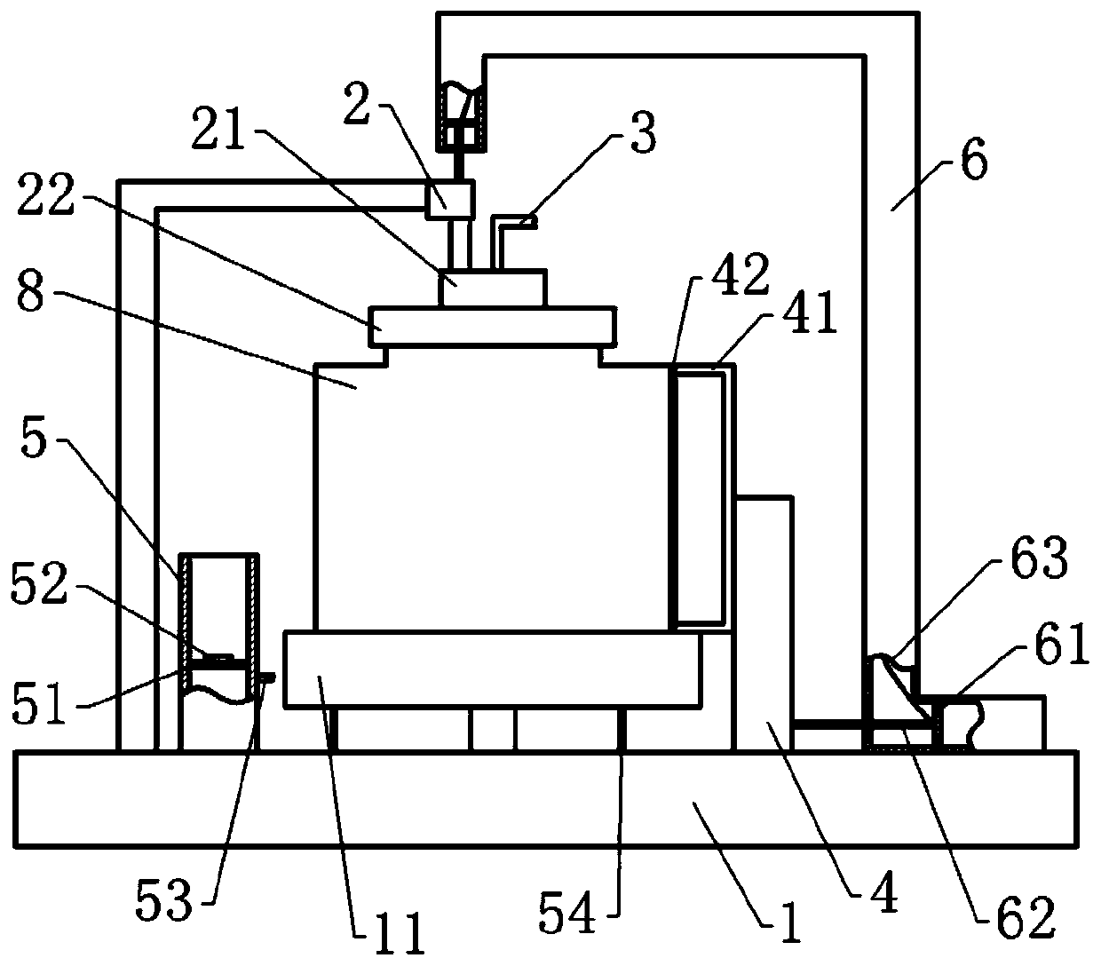
[0035] Pressure test instrument testing equipment, basically as attached figure 1 As shown, it includes a support platform 1, a detection part, an air intake part, an air suction part and a connecting piece 6. The support platform 1 is rotatably connected with a rotating block 11, and the upper surface of the rotating block 11 is provided with a mounting groove; the support platform 1 is embedded A motor is provided, and the drive shaft of the motor is fixed on the bottom of the rotating block 11 . Support frame 1 is also fixed with support frame, and lower pressure piece 2 is fixed on the support frame, and lower pressure piece 2 is the hydraulic expansion link that vertically arranges, and the bottom of hydraulic expansion link is fixed with lower pressing block 21, and the lower pressing block 21 The bottom is rotatably connected with a sealing cover 22 . Specifically, a rotating shaft is coaxially fixed on the top of the sealing cover 22 , and the rotating shaft passes th...

Embodiment 2

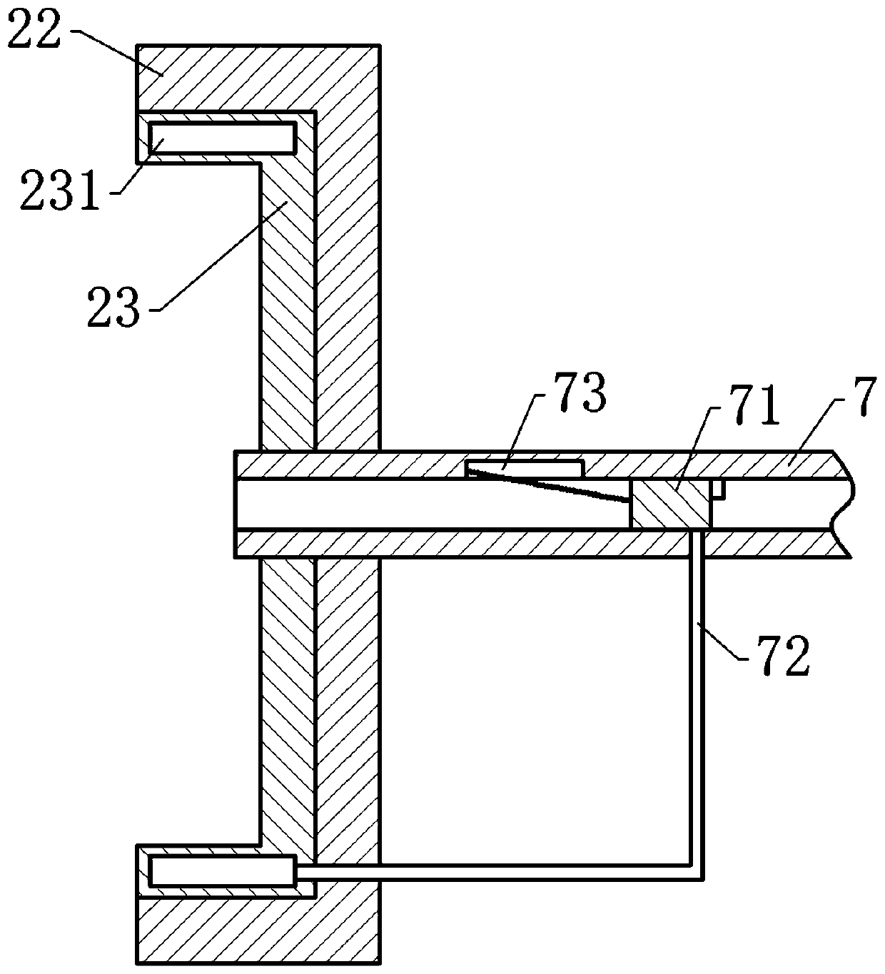
[0049] Embodiment 2 differs from Embodiment 1 only in that, as figure 2 As shown, the bottom of the sealing cover 22 is also fixed with a flexible sealing layer 23, and the flexible sealing layer 23 is provided with a cavity 231. The cavity 231 is connected with an inflatable part, and the inflatable part runs through the rotating shaft and is connected with the rotating shaft. Inflatable head 7. A sealing plate 71 is horizontally slidably connected in the inflatable head 7 , the inner wall of the inflatable head 7 is located at the left side of the sealing plate 71 and is provided with an air inlet gap 73 , and a spring is arranged between the air inlet gap 73 and the sealing plate 71 . An air duct 72 communicates with the inflatable head 7 below the sealing plate 71 , and the left end of the air duct 72 communicates with the cavity 231 in the flexible sealing layer 23 . The right end of the inflation head 7 communicates with the intake pipe 3 .

[0050] The specific implem...


PUM


Abstract

The invention, which belongs to the technical field of equipment for testing the sealing performance of a container through fluid, discloses pressure intensity experiment instrument detection equipment comprising a sealing cover and an air inlet part. The air inlet part comprises an air pump and an air inlet pipe communicated with the air pump, the air inlet pipe penetrates through the sealing cover. The pressure intensity experiment instrument detection equipment further comprises a supporting table, a vertical lower pressing piece is arranged on the supporting table, a pressing block is fixed to the bottom of the lower pressing piece, and the sealing cover is arranged at the bottom of the pressing block. The detection equipment further comprises a detection part including a frame body transversely connected to the supporting table in a sliding mode, a mounting frame is arranged on the frame body, two mounting strips are fixed to the mounting frame, and a thin film is fixed between the two mounting strips. Therefore, problems that in the prior art, after sealing performance detection is conducted, since a large amount of water adheres to a container, drying needs to be conducted,and operation is troublesome are solved.

Description

technical field [0001] The invention belongs to the technical field of equipment for testing the airtightness of a container by using a fluid, and in particular relates to a testing equipment for a pressure experiment instrument. Background technique [0002] Pressure experiment is a type of experiment often carried out in physics teaching, mainly used to intuitively express the relationship between pressure and flow velocity. Existing pressure test equipment usually includes a fluid generator, a container and an experimental part connected in sequence. A valve is arranged between the container and the experimental part. When in use, the fluid generator is used to introduce fluid into the container. When the container enters the laboratory After the required amount of fluid is used, open the valve and the fluid enters the experimental part through the container, and the experimental results can be obtained intuitively through the different flow rates of fluids with different...

Claims


Application Information

Patent Timeline
Patent Type & Authority Applications(China)
IPC IPC(8): G01M3/04G09B23/12
CPCG01M3/04G09B23/12
Inventor 程正富伏春平
Owner CHONGQING UNIV OF ARTS & SCI
Learn More