A numerical control machining drilling tool that can adjust the longitudinal height on the x and y axes arbitrarily

A technology of vertical height and processing drilling, which is applied in the direction of manufacturing tools, metal processing equipment, metal processing machinery parts, etc., can solve problems such as tool offset, affecting processing accuracy and quality, and fracture of telescopic devices, so as to improve the degree of freedom and improve The effect of fixing the strength of the installation and reducing the impact

Active Publication Date: 2021-05-18
赣州市志海精密科技有限公司
View PDF15 Cites 0 Cited by
  • Summary
  • Abstract
  • Description
  • Claims
  • Application Information

AI Technical Summary

Problems solved by technology

[0003] However, when the tool is installed and adjusted, the plane movement of the X and Y axes is easy to adjust. For the CNC drilling machine, the drilling force moves downward, causing the tool to have upward extrusion vibration, so that the existing telescopic rod, When the hydraulic cylinder and other devices realize up and down, due to the vibration and reaction force when the tool is drilling and cutting, it is very easy to cause problems such as tool offset or telescopic device breakage, which will affect the processing accuracy and quality
[0004] To this end, provide a CNC machining drilling tool that can adjust the longitudinal height arbitrarily on the X and Y axes to solve the problem of vertical height position adjustment and installation of the tool

Method used


Image

  • A numerical control machining drilling tool that can adjust the longitudinal height on the x and y axes arbitrarily
  • A numerical control machining drilling tool that can adjust the longitudinal height on the x and y axes arbitrarily
  • A numerical control machining drilling tool that can adjust the longitudinal height on the x and y axes arbitrarily

Examples


Embodiment Construction

[0026] The following will clearly and completely describe the technical solutions in the embodiments of the present invention with reference to the accompanying drawings in the embodiments of the present invention. Obviously, the described embodiments are only some, not all, embodiments of the present invention. Based on the embodiments of the present invention, all other embodiments obtained by persons of ordinary skill in the art without making creative efforts belong to the protection scope of the present invention.

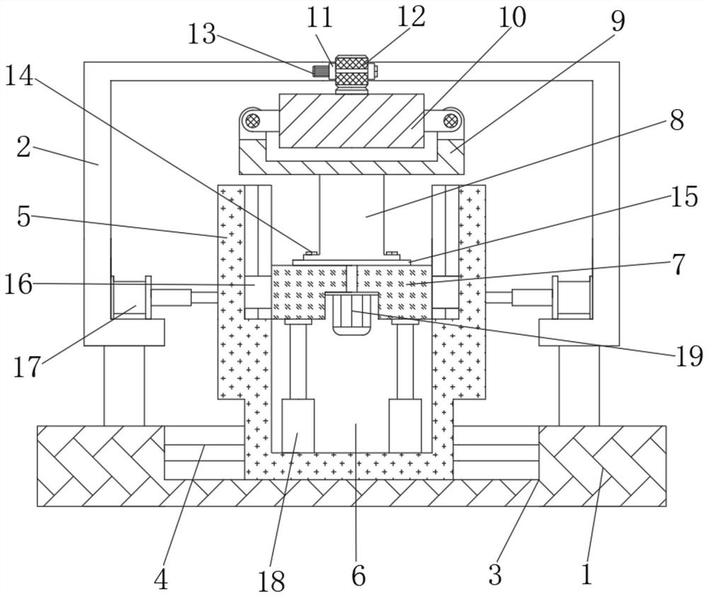
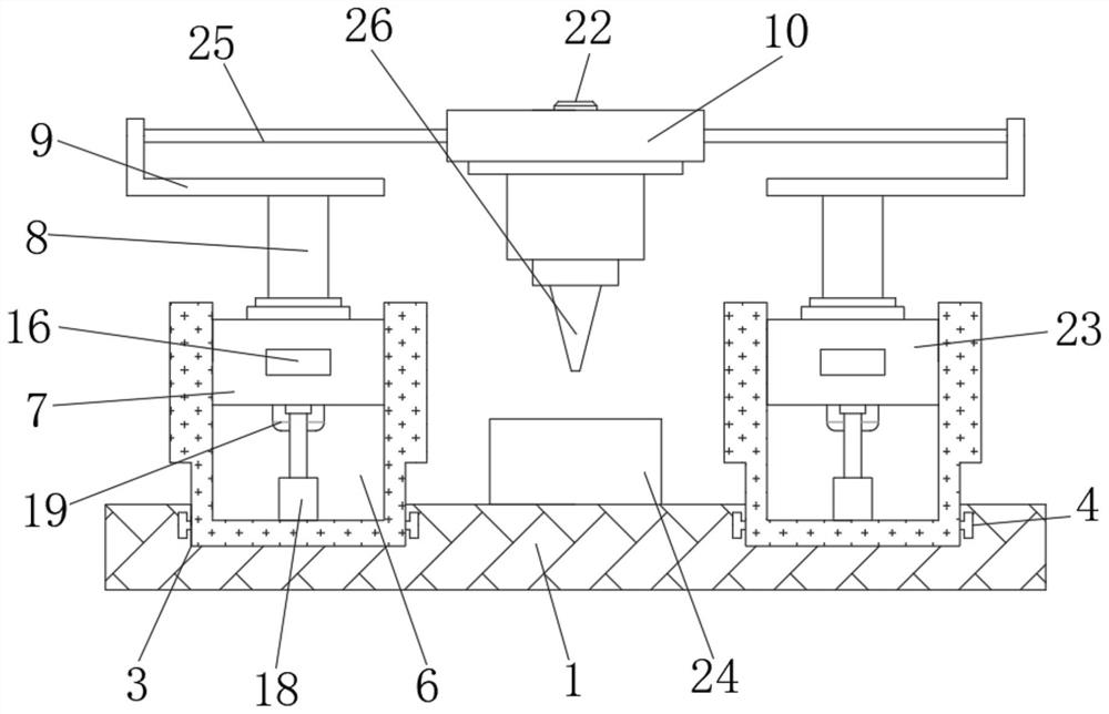
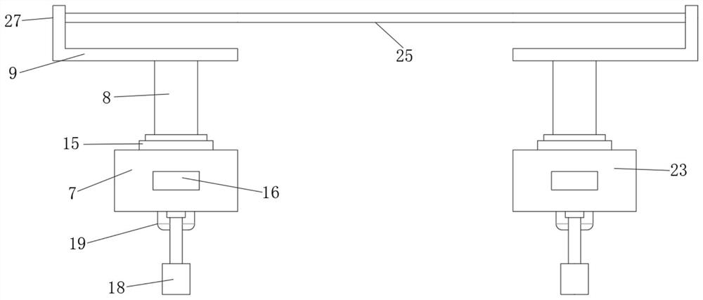
[0027] see Figure 1 to Figure 6 , the present invention provides a technical solution:

[0028] A CNC machining drilling tool that can adjust the longitudinal height on the X and Y axes arbitrarily, including a machine tool guide rail 1, a pair of left and right symmetrical horizontal adjustment grooves 3 are arranged in the middle of the upper end surface of the machine tool guide rail 1, and a left and right symmetrical pair of horizontal adjustment grooves...


PUM


Abstract

The invention relates to the technical field of numerical control machine tool processing, and specifically relates to a numerical control machining drilling tool which can adjust the longitudinal height on the X and Y axes arbitrarily, including a machine tool guide rail, and a pair of left and right symmetrical horizontal adjustment grooves are arranged in the middle of the upper end surface of the machine tool guide rail , the outer edge of the upper end surface of the machine tool guide rail is vertically welded with a mounting bracket, the beneficial effect is: the present invention realizes the position adjustment of the tool mounting device by arranging the cooperation of the hydraulic cylinder, the lifting cylinder and the meshing rotation of the rack and pinion, and then achieves X, The purpose of convenient position adjustment in the Y and Z directions, thereby improving the degree of freedom of machine tool processing; by setting the lifting cylinder to realize the vertical height adjustment of the tool installation device, the cooperation, the meshing of the gear and the rack, thereby limiting and reducing the tool installation device The vibration amplitude is high, because the gear buffers the upward reaction force during drilling, which greatly improves the installation and fixing strength of the tool installation device, and reduces the impact of the lifting device and processing quality due to vibration.

Description

technical field [0001] The invention relates to the technical field of numerical control machine tool processing, in particular to a numerical control machining drilling tool which can adjust the longitudinal height on the X and Y axes arbitrarily. Background technique [0002] With the advancement of CNC machine tool technology, the degree of freedom of axial adjustment during machine tool processing has gradually increased, and the X, Y, and Z three-axis movement of the tool position can be realized in the CNC machine tool. [0003] However, when the tool is installed and adjusted, the plane movement of the X and Y axes is easy to adjust. For the CNC drilling machine, the drilling force moves downward, causing the tool to have upward extrusion vibration, so that the existing telescopic rod, When the hydraulic cylinder and other devices are lifted up and down, due to the vibration and reaction force when the tool is drilling and cutting, it is very easy to cause problems su...

Claims


Application Information

Patent Timeline
Patent Type & Authority Patents(China)
IPC IPC(8): B23B39/16B23B47/20B23B47/22B23Q11/00
CPCB23B39/16B23Q5/26B23Q5/28B23Q11/0032
Inventor 方都
Owner 赣州市志海精密科技有限公司
Why Eureka
Try Eureka