
Cloth tube holder for mask production equipment

A technology of production equipment and cloth tube, which is applied in the field of cloth tube fixing frame for mask production equipment, which can solve the problems of cloth wrinkles, poor flanging effect, and inability to guarantee the setting position, etc., and achieve the effect of convenient feeding and cutting

Active Publication Date: 2021-08-31
ZHEJIANG LINIX MOTOR
View PDF15 Cites 0 Cited by
  • Summary
  • Abstract
  • Description
  • Claims
  • Application Information

AI Technical Summary

Problems solved by technology

After the fabric is used up, the cloth cylinder needs to be replaced. It cannot be guaranteed that the axial position of the cloth cylinder is the set position every time, and the axial position of the cloth cylinder needs to be debugged.
If the adjustment of the axial position of the cloth cylinder is not carried out, or the adjustment is not in place, the cloth in the subsequent feeding will be wrinkled, the effect of the subsequent flanging will be poor, and the masks produced will be unqualified

Method used


Image

  • Cloth tube holder for mask production equipment
  • Cloth tube holder for mask production equipment
  • Cloth tube holder for mask production equipment

Examples


Embodiment Construction

[0034] The present invention will be further described below according to the accompanying drawings and specific embodiments.

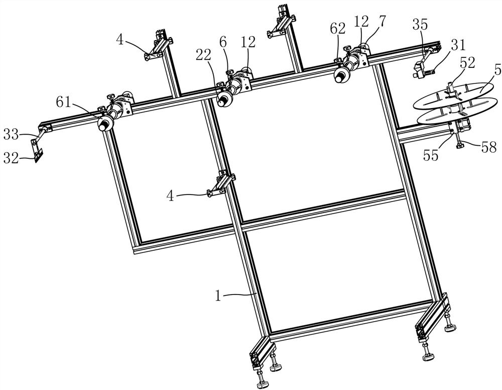
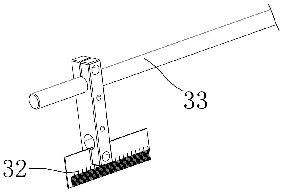
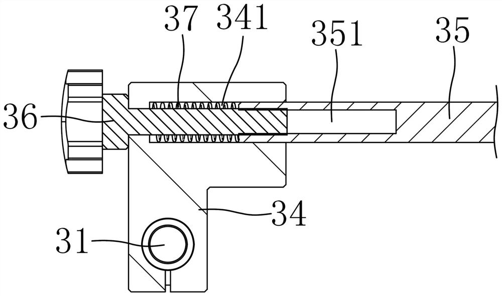
[0035] Depend on figure 1 , figure 2 , image 3 , Figure 7 , Figure 8 and Figure 9 As shown, a cloth tube fixing frame for mask production equipment of the present invention comprises a frame body 1, three fixed shafts 2 arranged side by side are arranged on the frame body 1, and a fixed tube 6 is sleeved on the fixed shaft 2, and the fixed shaft Located on the same side of the left and right sides of the frame body 1, the fixed shafts 2 are arranged along the left and right directions, and the axes of the fixed shafts 2 are arranged parallel to each other. The side of the frame body 1 with the fixed shaft 2 is provided with a detection component, and the detection component includes a laser transmitter. 31 and the reference piece 32 , the fixed shaft 2 is located between the laser emitter 31 and the reference piece 32 , the laser emitter 31 ...


PUM


Abstract

The purpose of the present invention is to provide a cloth tube fixing frame for mask production equipment which is convenient for adjusting the axial position of the cloth tube. In order to achieve the above object, the present invention adopts the following technical scheme: a cloth tube fixing frame for mask production equipment, including a frame body, and the frame body is provided with several fixed shafts arranged side by side, and the fixed shafts are located on the left and right sides of the frame body. On the same side, the fixed shafts are arranged along the left and right directions, and the axes of the fixed shafts are arranged parallel to each other. The side of the frame body provided with the fixed shafts is provided with a detection assembly, and the detection assembly includes a laser emitter and a reference piece. The axes are each located between a laser emitter that emits laser light forward or backward and irradiates the laser light on the reference piece, and the reference piece.

Description

technical field [0001] The invention relates to mask production equipment, in particular to a cloth cylinder fixing frame for mask production equipment. Background technique [0002] The mask production equipment includes a fixed frame for placing non-woven fabrics and other materials. The fixed frame is equipped with an optical axis, and the cloth tube is sleeved on the optical axis, and then fed through the feeding mechanism. After the fabric is used up, the cloth cylinder needs to be replaced, and the axial position of the cloth cylinder cannot be guaranteed to be the set position every time. It is necessary to debug the axial position of the cloth cylinder. If the adjustment of the axial position of the cloth cylinder is not carried out, or the adjustment is not in place, the cloth in the subsequent feeding will be wrinkled, the effect of the subsequent flanging will be poor, and the masks produced will be unqualified. Contents of the invention [0003] The purpose of...

Claims


Application Information

Patent Timeline
Patent Type & Authority Patents(China)
IPC IPC(8): B65H23/038B65H23/26B65H26/00
CPCB65H23/038B65H23/26B65H26/00B65H2515/31B65H2511/24
Inventor 朱智平任凯乐杜姗杜熠瑾
Owner ZHEJIANG LINIX MOTOR
Learn More