Water conservancy project retaining wall

A technology for water conservancy projects and retaining walls, applied in water conservancy projects, infrastructure engineering, artificial islands, etc., can solve problems such as blockage of filter screens and affect the normal drainage work, so as to protect the retaining walls and reduce the difficulty of maintenance Effect

Inactive Publication Date: 2020-06-30
赵金玉
View PDF10 Cites 2 Cited by
  • Summary
  • Abstract
  • Description
  • Claims
  • Application Information

AI Technical Summary

Problems solved by technology

In order to ensure smooth drainage, the existing retaining walls will be provided with drainage channels and water inlets connected to the drainage channels, and then set filter screens at the water inlets to intercept the sediment, but this will easily cause the filter screens to be blocked by sediment. Blockage, thus affecting the normal drainage work

Method used


Image

  • Water conservancy project retaining wall
  • Water conservancy project retaining wall
  • Water conservancy project retaining wall

Examples


Embodiment 1

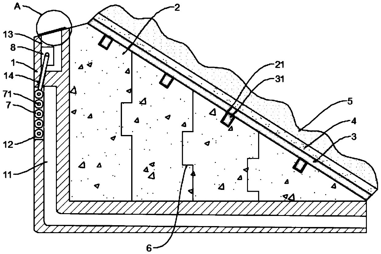
[0022] See Figure 1~3 In the embodiment of the present invention, a retaining wall for a water conservancy project includes a mounting seat 1 and a retaining wall provided on the mounting seat 1. The mounting seat 1 is provided with a connected drainage channel 11 and a water inlet 12, and the water inlet 12 is arranged on the side of the mounting seat 1 close to the foundation soil; a plurality of rotating rollers 7 arranged equidistantly are installed in the water inlet 12, and the rotating rollers 7 are rotatably connected to the water inlet 12 through a rotating shaft 71, and adjacent rotating rollers There is a gap between 7 so that water can circulate. The adjacent rotating shafts 71 are connected by a first belt pair transmission. The mounting seat 1 is equipped with a driving device 8 for driving one of the rotating shafts 71 to rotate. During normal operation, the water It flows into the drainage channel 11 through the gap between the rollers 7 for normal drainage. Wh...

Embodiment 2

[0027] The embodiment of the present invention expands its functions on the basis of embodiment 1. Specifically:

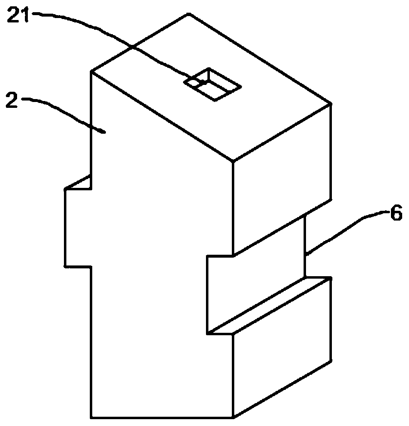
[0028] The retaining wall is composed of multiple wall units 2. The wall unit 2 is fixed on the mounting base 1 by bolts, so that when the wall is partially damaged, only one of the wall units 2 needs to be replaced. Perform overall disassembly.

[0029] In order to ensure the connection strength of the adjacent wall units 2, in this embodiment, the adjacent wall units 2 are connected by a locking structure 6, and the locking mechanism 6 includes a recess integrally formed in one of the wall units 2. The concave portion and the convex portion integrally formed on the other wall unit 2 are embedded in the concave portion and the convex portion. The cooperating arrangement of the concave portion and the convex portion can improve the connection strength of the adjacent wall unit 2.

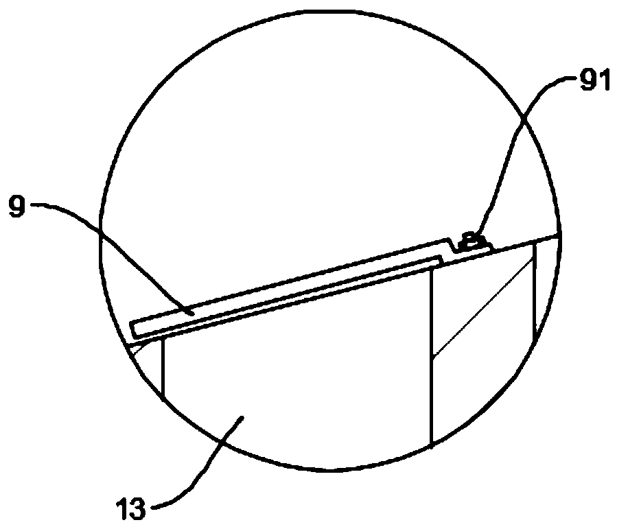
[0030] Further, the outer surface of the retaining wall is provided with a waterproof lay...


PUM


Abstract

The invention discloses a water conservancy project retaining wall. The water conservancy project retaining wall comprises a mounting seat and a retaining wall body arranged on the mounting seat, wherein a drainage channel and a water inlet which communicate are formed in the mounting seat, and the water inlet is arranged on one side, close to a foundation soil body, of the mounting seat; a plurality of rotating rollers arranged at equal intervals are mounted in the water inlet, the rotating rollers are rotatably connected with the water inlet through rotating shafts, and a gap is formed between adjacent rotating rollers, so that water can flow; and the adjacent rotating shafts are in transmission connection through a first belt pair, and a driving device for driving one rotating shaft torotate is mounted in the mounting seat. According to the water conservancy project retaining wall, by arranging the multiple rotating rollers arranged at intervals in the water inlet, intercepting ofsilt can be achieved, normal passing of the water flow can be guaranteed, the silt in the gaps can be extruded out through driving the rotating rollers when the water inlet is blocked, the dredge workof the water inlet is completed, normal operation of the drainage is guaranteed, and the problem in the prior art is solved.

Description

Technical field [0001] The invention relates to the field of water conservancy projects, in particular to a retaining wall for water conservancy projects. Background technique [0002] A water conservancy project is a project built for the purpose of controlling and arranging surface water and groundwater in the natural world to achieve the purpose of eliminating harm and benefiting. Also called water engineering. Water is a precious resource indispensable for human production and life, but its natural state does not fully meet human needs. Only by building water conservancy projects can we control water flow, prevent floods, and regulate and distribute water volume to meet the needs of people for water resources in life and production. [0003] Retaining wall is a common structure in water conservancy projects. Its main function is to support subgrade fill or hillside soil and prevent the fill or soil from deformation and instability. In order to ensure smooth drainage, the exi...

Claims


Application Information

Patent Timeline
Patent Type & Authority Applications(China)
IPC IPC(8): E02D29/02E02D17/20E03F3/02E03F5/14E03F7/00
CPCE02D29/02E02D29/0266E02D17/20E03F3/02E03F5/14E03F7/00E02D2600/20
Inventor 赵金玉刘维浩
Owner 赵金玉
Why Eureka
Try Eureka