Water tank structure for load test, test device and test method

A technology of load test and test method, applied in basic structure engineering, basic structure test, construction, etc., can solve the problems of inconvenient transportation and loading and unloading, long service cycle, etc., and achieve convenient and fast transportation and loading and unloading, safe stacking, and avoid waste. Time and manpower and the effect of inconvenient transportation

Pending Publication Date: 2020-06-30
CHINA NORTHWEST ARCHITECTURE DESIGN & RES INST CO LTD
View PDF0 Cites 4 Cited by
  • Summary
  • Abstract
  • Description
  • Claims
  • Application Information

AI Technical Summary

Problems solved by technology

[0003] The purpose of the present invention is to overcome the problems of long service life and inconvenient transportation and loading and unloading caused by using concrete test block as the loading device in the existing load test

Method used


Image

  • Water tank structure for load test, test device and test method
  • Water tank structure for load test, test device and test method
  • Water tank structure for load test, test device and test method

Examples


Embodiment 1

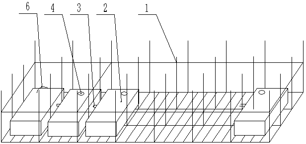
[0025] The present embodiment provides a kind of water tank structure that is used for load test, as figure 1 As shown, it includes several water tanks 2 that are evenly distributed in layers and stacked on the support 1, and the adjacent water tanks 2 on each layer are connected through connecting water pipes 3, and each water tank 2 is provided with a water inlet 4 and a water discharge port 5 , the detachable sealing cover is installed on the 5 ends of the water discharge port, and the water inlet 4 is located on the top surface of the water tank 2 and is connected to the water pump through the detachable water inlet pipe 6 .

[0026] Both the detachable water inlet pipe 6 and the water outlet 5 ends are equipped with automatic flow control devices. The water inlet 4 of at least one of the water tanks 2 on each floor is connected to the water pump through a detachable water inlet pipe 6 . All adjacent water tanks 2 are connected by connecting plates, and the connecting pla...

Embodiment 2

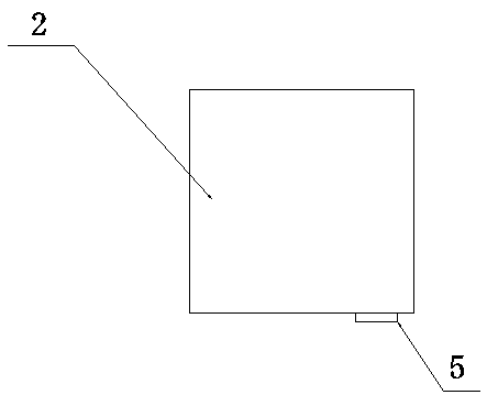
[0039] On the basis of Example 1, in order to facilitate uninstallation, such as figure 2 As shown, in this embodiment, the drain port 5 is opened on the bottom surface of the water tank 2 . Specifically, when unloading, open the drain port 5 on the bottom plate of each water tank 2, the water in the water tank 2 flows out from the drain port, and because the drain port 5 is provided on the bottom surface of the water tank 2, it can ensure that the water in the water tank 2 is completely unloaded.

Embodiment 3

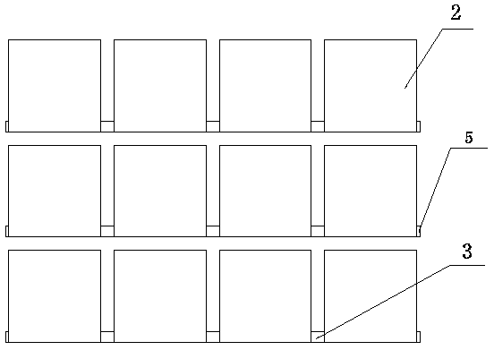
[0041] On the basis of Example 1, such as image 3 and Figure 4 As shown, each side wall of the water tank 2 is respectively provided with a drain opening 5 near the bottom plate, and the drain openings 5 ​​on the opposite side walls of the two adjacent water tanks 2 on each floor are used as connection ports for connecting the water pipes 3 .

[0042] Specifically, this embodiment takes a rectangular water tank as an example (it is not limited thereto, it can also be a water tank of other shapes), the top surface of each rectangular water tank is provided with a water inlet 4, and the water inlet 4 is connected to a detachable water inlet pipe 6, The detachable water inlet pipe 6 is connected to the running water pipe on the construction site, or the detachable water inlet pipe 6 is connected to the water pump, and the water pump is placed in the water storage tank or the water storage tank; in particular, each of the four side walls of the rectangular water tank is provided...


PUM


Abstract

The invention provides a water tank structure for a load test, a test device and a test method. The water tank structure comprises a plurality of water tanks which are uniformly distributed layer by layer and stacked on a support, adjacent water tanks of each layer are communicated through a connecting water pipe, a top surface of each water tank is provided with a water inlet, the bottom surfaceof each water tank is provided with a water outlet, the water inlet is connected with a water pump through a detachable water inlet pipe, and a detachable sealing cover is installed at a water outletend. According to the wate tank structure for the load test and the load test method provided by the invention, the water tank is used as a loading device for the load test, a corresponding number ofwater tanks are assembled according to the load requirement, water is injected into the water tank during loading, and water in the water tank is discharged during unloading, so that one-time water filling and one-time water discharging are realized; the problems that time and labor are wasted and transportation is inconvenient due to transportation and stacking of concrete blocks or sand bags aresolved, meanwhile, the water tanks are safe to stack, water filling and water discharging are rapid, repeated utilization can be achieved, and transportation, loading and unloading are more convenient and faster.

Description

technical field [0001] The invention relates to a device for measuring foundation bearing capacity, in particular to a water tank structure, a test device and a test method for load tests. Background technique [0002] Static load test: according to the use function of the pile, apply axial pressure, axial upward pullout force on the top of the pile step by step, or apply horizontal force at the same elevation of the bottom surface of the pile foundation cap, and observe the corresponding detection points of the pile over time. The resulting settlement, uplift displacement or horizontal displacement, according to the relationship between load and displacement to determine the corresponding single pile vertical compressive bearing capacity, single pile vertical pullout bearing capacity or single pile horizontal bearing capacity test method, it is currently It is the most widely used method among the various methods for testing the bearing capacity of pile foundations, and it ...

Claims


Application Information

Patent Timeline
Patent Type & Authority Applications(China)
IPC IPC(8): E02D33/00
CPCE02D33/00
Inventor 史生志辛力杨琦荆罡
Owner CHINA NORTHWEST ARCHITECTURE DESIGN & RES INST CO LTD
Why Eureka
Try Eureka