
Medium and high-rise building lighting system

A technology for lighting systems and high-rise buildings, applied in buildings, ventilation systems, lighting devices, etc., can solve problems affecting living comfort, temperature rise, etc., achieve good energy-saving effects, avoid rainwater entry, and have good practicability

Active Publication Date: 2021-03-23
深圳机械院建筑设计有限公司
View PDF10 Cites 0 Cited by
  • Summary
  • Abstract
  • Description
  • Claims
  • Application Information

AI Technical Summary

Problems solved by technology

[0003] Although it satisfies the ventilation and lighting of the building during use, in hot summer, the sunlight will directly shine into the house, which will easily lead to an increase in the temperature inside the house and affect the living comfort.

Method used


Image

  • Medium and high-rise building lighting system
  • Medium and high-rise building lighting system

Examples


Embodiment 1

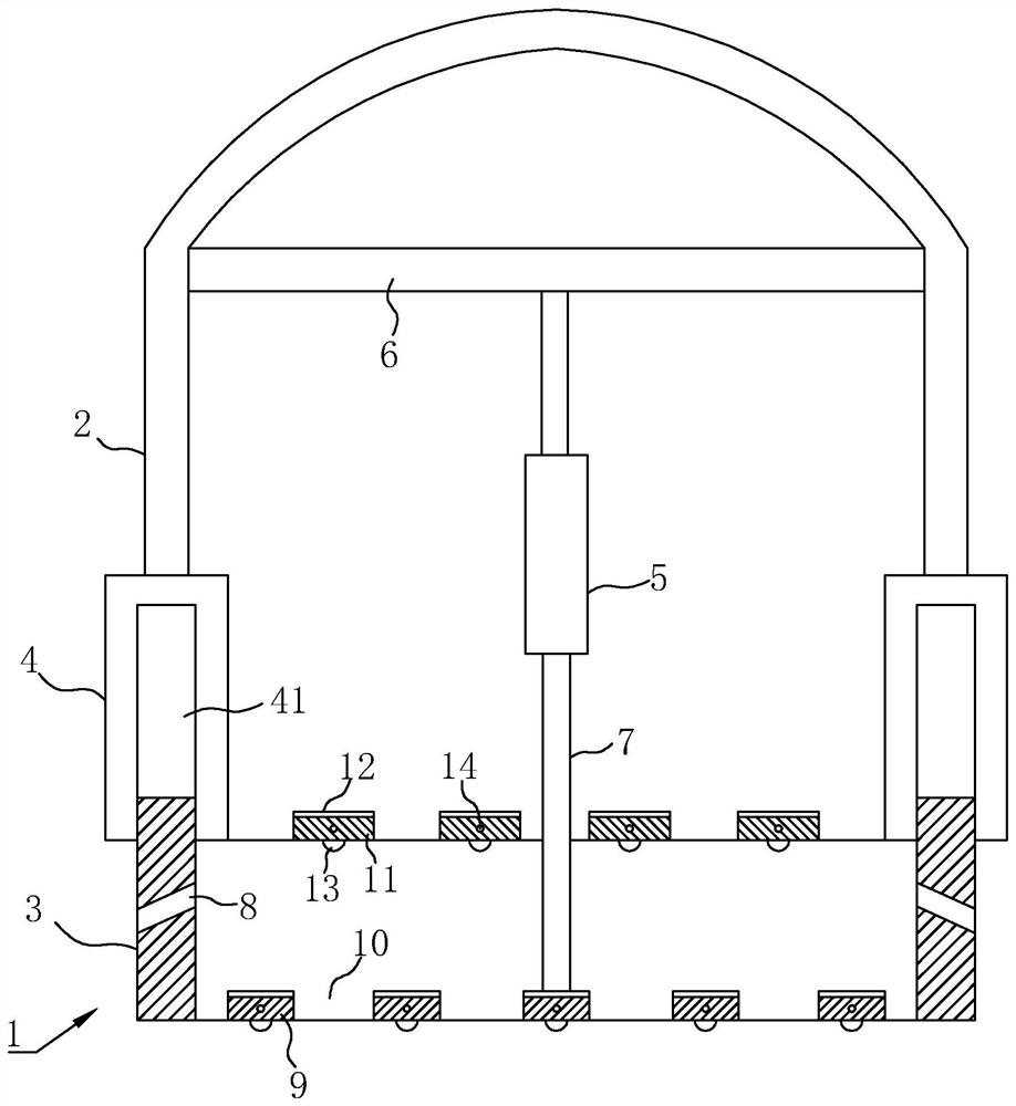
[0034] Embodiment 1: refer to figure 1 , is a daylighting and lighting system for medium and high-rise buildings disclosed by the present invention, comprising a base frame 1 and a skylight 2 located above the base frame 1, the skylight 2 is made of transparent plastic or glass, and is vertically slidably connected to the base frame 1 The underframe 1 includes a vertical first connecting portion 3 extending on both sides, and the first connecting portion 3 is in the shape of a vertical bar; wherein the skylight 2 includes a ceiling and a side plate below, and the bottom of the side plate is fixedly connected with a The second connecting part 4 connected to the first connecting part 3 is U-shaped and the middle part forms a slot 41 for the insertion of the first connecting part 3 and vertical sliding, and is fixed inside the chassis 1 There is a driving member for driving the skylight 2 to slide vertically, the driving member includes a cylinder 5, the cylinder 5 is vertically ...

Embodiment 2

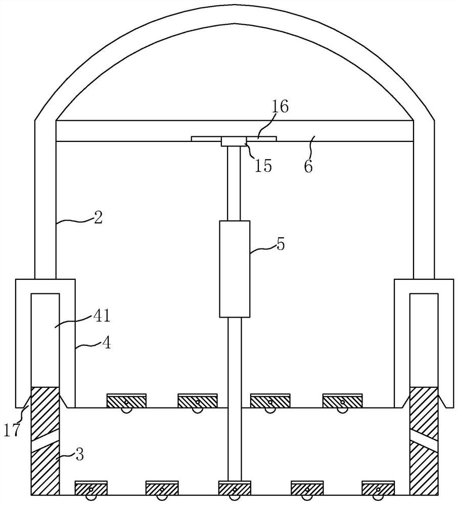
[0039] Embodiment 2: refer to figure 2 , is a daylighting and lighting system for medium and high-rise buildings disclosed by the present invention. The difference between it and Embodiment 1 is that the end of the piston rod of the cylinder 5 is horizontally slidably connected with the cross bar 6, and a slider is fixed on the top of the piston rod of the cylinder 5. 15. At the same time, the bottom wall of the cross bar 6 is provided with a chute 16 that is horizontally slidably connected with the slider 15. The vertical sections of the slider 15 and the chute 16 are T-shaped, so that when the two are slidably connected At the same time, the state of vertical linkage is realized; this can effectively cooperate with the insertion of the slot 41 on the second connection part 4 and the first connection part 3, and avoid the slight deviation between the two, which will cause the two to be stuck and difficult to plug in and fit.

[0040] In addition, the opening 17 of the slot 4...


PUM


Abstract

The invention relates to a lighting and illuminating system for a mid-rise building. The lighting and illuminating system comprises a bottom frame and a transparent skylight. The skylight is vertically and slidingly connected to the bottom frame. The bottom frame is provided with a driver for driving the skylight to rise or fall. Shielding strips are arranged in the middle of the bottom frame at intervals. Through grooves are formed between the adjacent shielding strips. Partitioning strips matched with the through grooves are arranged in the skylight at intervals. By arranging the partitioning strips and the shielding strips at intervals in a staggered mode, when lighting is needed, the skylight is driven by the driver to move up, so that the effective height difference is formed betweenthe shielding strips and the partitioning strips; at the moment, sunlight can illuminate the indoor space through the through grooves, so that the good lighting effect is realized; in this period, thelighting effect can be adjusted by adjusting the shielding strips and the partitioning strips; in the hot summer, the skylight is driven to move down, so that the partitioning strips are matched withthe through grooves; and at the moment, the through grooves are closed, so that the comprehensive light shielding aim is realized, external sunlight cannot illuminate the indoor space, and the adverse effect caused when sunlight illuminates the indoor space in summer is well avoided.

Description

technical field [0001] The invention relates to the technical field of buildings, in particular to a daylighting and lighting system for middle and high-rise buildings. Background technique [0002] At present, with the continuous progress of society, the functions of buildings are gradually diversified, such as meeting the needs of lighting, ventilation and other aspects. In the prior art, for example, the Chinese patent with the announcement number CN209568624U discloses a civil building Daylighting and ventilation skylights, including skylight brackets, ventilation holes, empty slots, pistons, skylights, horizontal plates, first lifting lugs, connecting shafts, connecting rods, second lifting lugs, connecting shafts, lifting columns, vertical rods, pneumatic cylinders, base Seat, pillar, fixed seat and connecting column, the upper side of the skylight bracket is provided with a ventilation hole, the piston is arranged in the empty groove, the upper end of the piston is pr...

Claims


Application Information

Patent Timeline
Patent Type & Authority Patents(China)
IPC IPC(8): E04D13/035E04D13/17F21S9/03
CPCE04D13/035E04D13/17F21S9/035Y02B10/10
Inventor 向雪薇江莉王斯泽
Owner 深圳机械院建筑设计有限公司
Learn More