Steam circulating energy storage system for water thermal storage

A technology of energy storage system and hot steam, applied in heat storage equipment, steam generation, steam generation method, etc., can solve the problems affecting the normal use of equipment and water storage, and achieve the effect of improving magnetization efficiency, compact structure, and avoiding scale

Pending Publication Date: 2020-06-30
上海中如智慧能源集团有限公司
View PDF0 Cites 2 Cited by
  • Summary
  • Abstract
  • Description
  • Claims
  • Application Information

AI Technical Summary

Problems solved by technology

[0006] In view of this, the purpose of the present invention is to provide a steam cycle energy storage system for water heat storage to solve the problem that the traditional steam equipment for water heat storage energy storage in the prior art cannot store and generate hot water at different temperatures according to the needs of use. problem, and further solve the problem that traditional water heat storage steam equipment is easy to affect the normal use of equipment and water storage due to scale

Method used


Image

  • Steam circulating energy storage system for water thermal storage
  • Steam circulating energy storage system for water thermal storage
  • Steam circulating energy storage system for water thermal storage

Examples


Embodiment Construction

[0037] In order to make the purpose, technical solutions and advantages of the embodiments of the present invention clearer, the technical solutions in the embodiments of the present invention will be clearly and completely described below in conjunction with the drawings in the embodiments of the present invention. Obviously, the described embodiments It is a part of embodiments of the present invention, but not all embodiments. The components of the embodiments of the invention generally described and illustrated in the figures herein may be arranged and designed in a variety of different configurations.

[0038] Accordingly, the following detailed description of the embodiments of the invention provided in the accompanying drawings is not intended to limit the scope of the claimed invention, but merely represents selected embodiments of the invention. Based on the embodiments of the present invention, all other embodiments obtained by persons of ordinary skill in the art wi...


PUM


Abstract

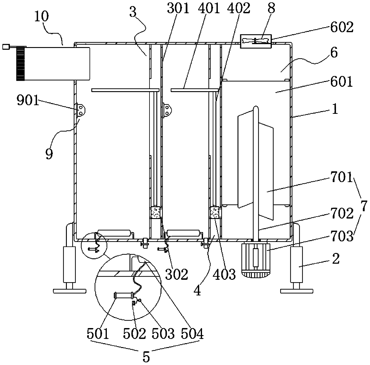
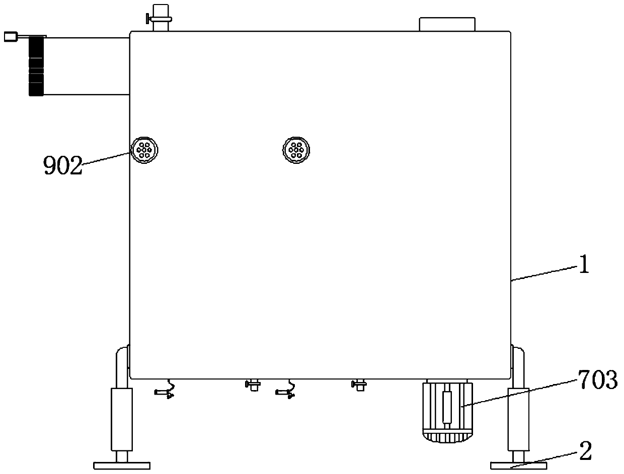
The invention relates to a steam circulating energy storage system for water thermal storage. The steam circulating energy storage system for the water thermal storage comprises a box body and supporting columns, wherein the box body has a hollow structure inside and is used for storing retain water, and the supporting columns are arranged on both sides of the box body for supporting the box body.The steam circulating energy storage system for the water thermal storage is characterized by further comprising two groups of separation assemblies, a heating assembly and a hot steam assembly, wherein the separation assemblies are capable of separating the retain water, the heating assembly is capable of controllably heating the separated retain water, and the hot steam assembly is used for producing hot steam; and the two groups of the separation components act on the interior of the box body together to divide the interior of the box body into three independent cavities, two adjacent independent cavities can store the retain water at different temperatures, and the other independent cavity can store the hot steam. The steam circulating energy storage system for the water thermal storage has a coherent and compact structure, so that the problem that traditional steam equipment for water thermal storage and energy storage can not store and generate hot water at different temperatures according to the needs of use is solved, and the problem that traditional water thermal storage steam equipment is prone to affecting the normal use of the equipment and the retain water due to scale is further solved.

Description

technical field [0001] The invention relates to the technical field of water heat storage, in particular to a steam cycle energy storage system for water heat storage. Background technique [0002] With the continuous development of the times, the society's research on water heat storage energy storage technology has gradually become the focus of contemporary society. The traditional steam equipment for water heat storage can no longer meet the high standard use needs of contemporary society. The disadvantages are explained as follows: [0003] 1. The traditional steam equipment for water heat storage and energy storage cannot selectively supply energy storage water at different temperatures for use according to actual needs during use. Centralized heating of the water storage is still adopted and further diverted by external heating equipment. Supply and use, thereby increasing too much financial and material resources in the installation process and use process. [0004]...

Claims


Application Information

Patent Timeline
Patent Type & Authority Applications(China)
IPC IPC(8): F22B1/28C02F1/48F28D20/00
CPCC02F1/481C02F2303/22F22B1/28F28D20/0034Y02E60/14
Inventor 周协峰
Owner 上海中如智慧能源集团有限公司
Why Eureka
Try Eureka