
Impact resistance testing device and method for anti-glare panel

A technology of impact resistance and test equipment, applied in the direction of measuring equipment, strength characteristics, instruments, etc., can solve the problems of inability to effectively control the height of the falling ball, inaccurate test results, inconvenient operation, etc., to achieve consistent falling speed and ensure accuracy , the effect of reducing the experimental error

Active Publication Date: 2020-06-30
河北交规院瑞志交通技术咨询有限公司
View PDF19 Cites 1 Cited by
  • Summary
  • Abstract
  • Description
  • Claims
  • Application Information

AI Technical Summary

Problems solved by technology

In traditional operation, manual operation is generally adopted, that is, the way of holding the steel ball, which is very inconvenient to operate and cannot effectively control the height of the falling ball, resulting in inaccurate test results and large errors

Method used


Image

  • Impact resistance testing device and method for anti-glare panel
  • Impact resistance testing device and method for anti-glare panel

Examples


Embodiment Construction

[0036] The present invention will be described in further detail below in conjunction with the accompanying drawings.

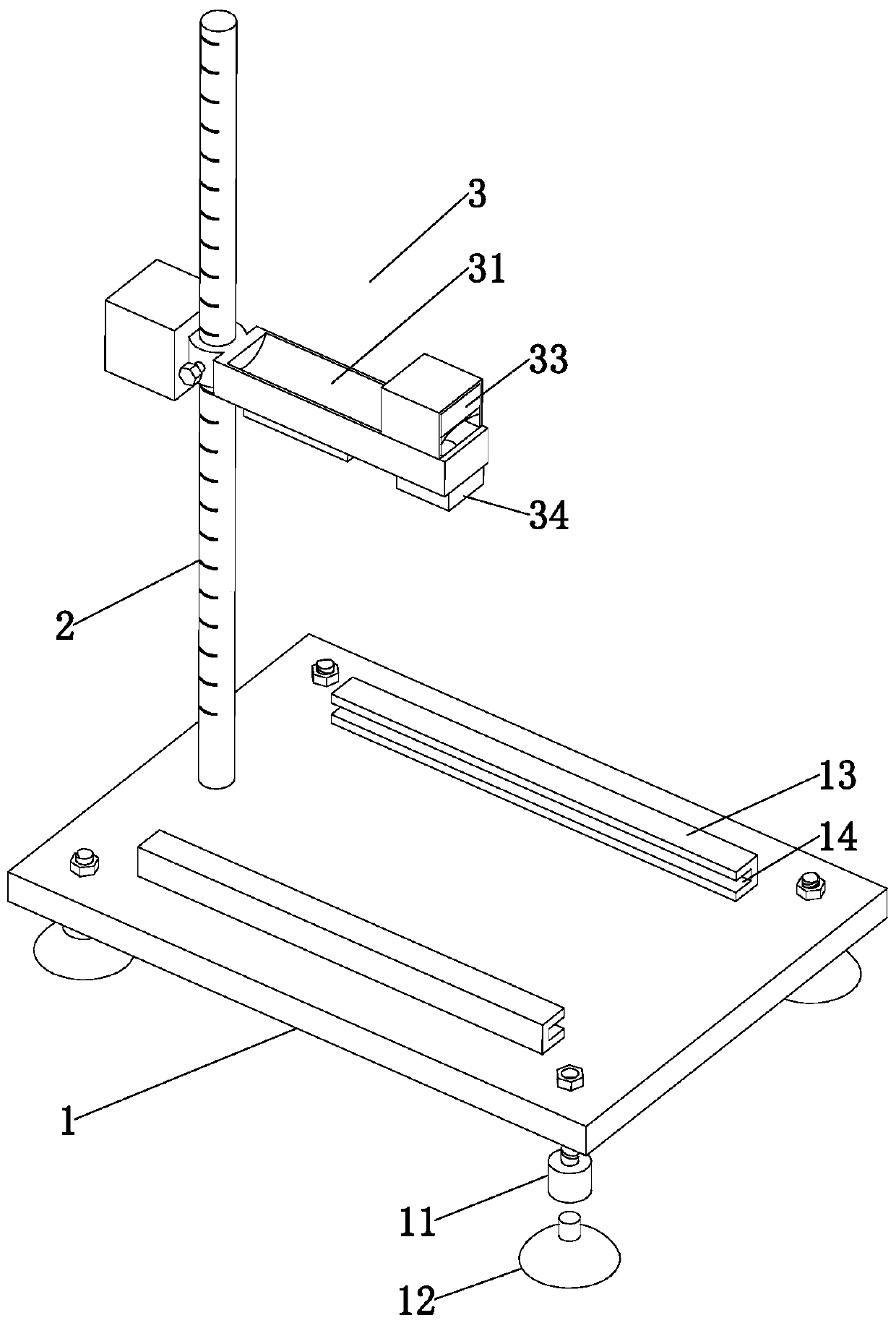
[0037] refer to figure 1 , is an anti-glare plate impact performance test device disclosed in the present invention, including a base 1, a column 2 arranged on the base 1, and a ball drop frame 3 slidably arranged on the column 2.

[0038] The base 1 is set as a rectangular plate structure. In this embodiment, the base 1 is set as an aluminum plate, and the lower part of the base 1 is provided with legs 11. In this embodiment, the base 1 is provided with four legs 11, which are respectively arranged on four sides of the base 1. At the top corner position, the supporting leg 11 enables the device to be placed in the test on an uneven working surface, reducing the influence of the working surface on the test results; the upper end of the supporting leg 11 has a small diameter, is provided with threads, and passes through the base 1 to the upper surface of the ...


PUM


Abstract

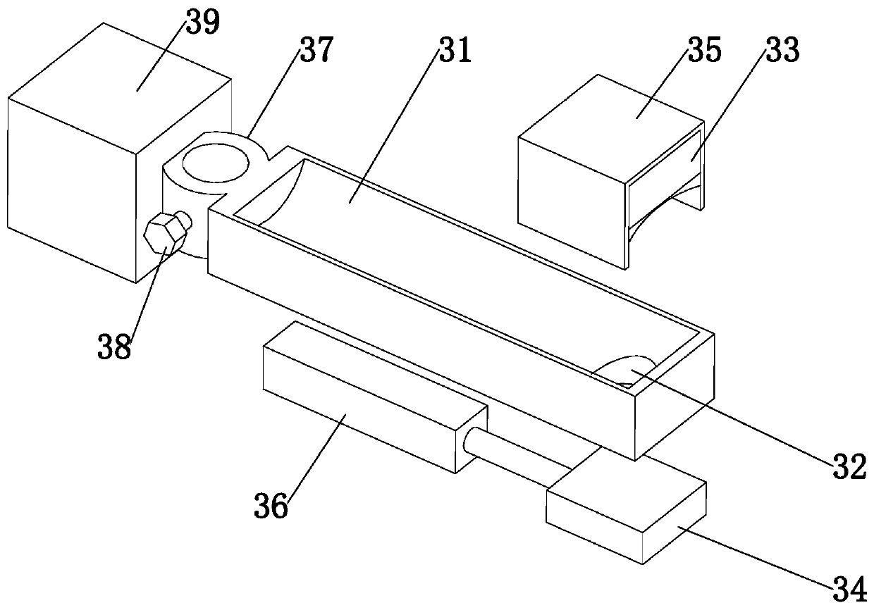
The invention relates to an impact resistance testing device for an anti-glare panel. The impact resistance testing device comprises a base, a stand column arranged on the base and a ball falling frame arranged on the stand column in a sliding mode. The ball falling frame is arranged on the stand column in a sleeving mode. A falling ball placing groove is formed in one end; a falling ball fallingopening is formed in the end part of the falling ball placing groove; an electromagnetic chuck is arranged above the falling ball falling opening; a sealing door for opening and closing the falling ball falling opening is arranged below the falling ball falling opening; a supporting frame is arranged above the end of the falling ball frame, the electromagnetic chuck is connected to the supportingframe, a spherical surface with a downward opening is arranged on the lower surface of the electromagnetic chuck, and the vertex of the spherical surface of the electromagnetic chuck corresponds to the central axis of the falling ball falling opening up and down. According to the test device, the falling height of the falling ball can be adjusted, it is guaranteed that the falling height of the falling ball is consistent, and test results are more accurate.

Description

technical field [0001] The invention relates to the technical field of traffic facility detection, in particular to a device and method for testing the impact resistance of an anti-glare board. Background technique [0002] The anti-glare board is a traffic safety product manufactured and installed on the central divider of the expressway to solve the glare of the opposite headlights. Its impact resistance is an important indicator of its performance. [0003] The impact resistance of anti-glare panels is generally achieved through the falling ball impact test. Its traditional operation method is to raise the falling ball to a certain height and then put the ball down so that it falls naturally to form an impact on the anti-glare board. In the traditional operation, manual operation is generally used, that is, the way of holding the steel ball, which is very inconvenient to operate and cannot effectively control the height of the falling ball, resulting in inaccurate test r...

Claims


Application Information

Patent Timeline
IPC IPC(8): G01N3/303G01N3/02
CPCG01N3/303G01N3/02
Inventor 崔晟东张悦孙斌刘冬宁何方超张谦
Owner 河北交规院瑞志交通技术咨询有限公司
Learn More