Multi-group hydraulic linkage lifting mechanism

A lifting mechanism and hydraulic linkage technology, which is applied in the direction of lifting frame and lifting device, can solve the problems of deep installation pit of the lift, small lifting range, and inconvenient maintenance of the lift, so as to improve the lifting effect and install And the effect of easy maintenance and high market application value

Inactive Publication Date: 2020-07-03
界首市神机合自动化科技有限公司
View PDF1 Cites 2 Cited by
  • Summary
  • Abstract
  • Description
  • Claims
  • Application Information

AI Technical Summary

Problems solved by technology

In this patent document, the hydraulic device is vertically fixed on the support ribs, which makes the lifting range smaller, and because the lift needs to be installed below the ground, this also causes the installation pit of the lift to be relatively large. Deep, which brings inconvenience to the maintenance of the lift

Method used


Image

  • Multi-group hydraulic linkage lifting mechanism
  • Multi-group hydraulic linkage lifting mechanism
  • Multi-group hydraulic linkage lifting mechanism

Examples


specific Embodiment 1

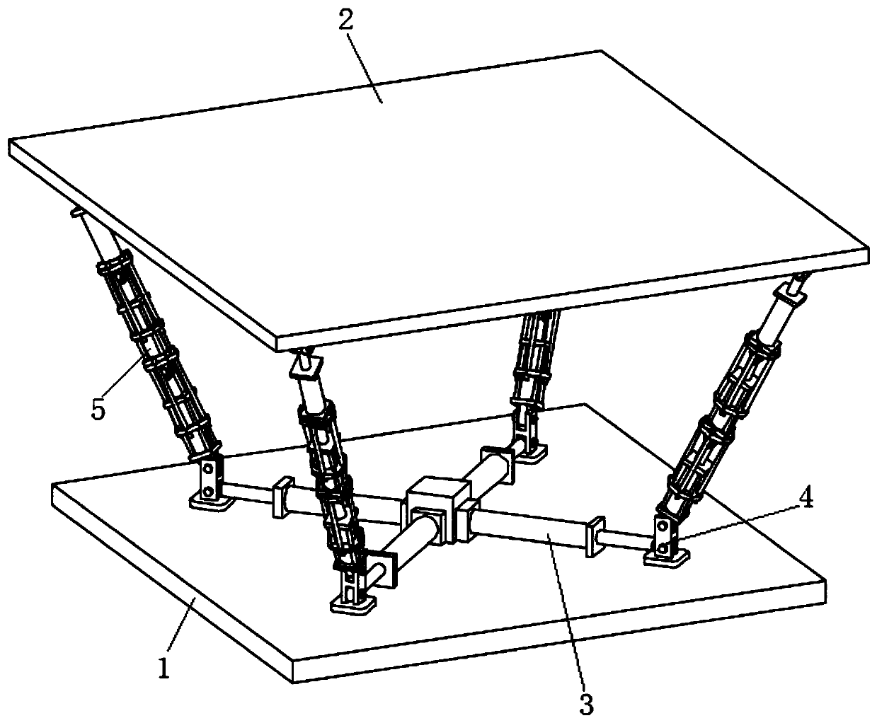
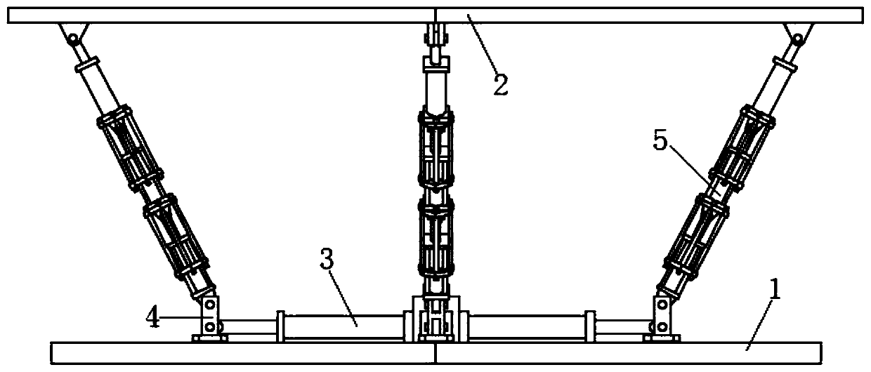
[0026] see Figure 1-5 As shown, the present invention is a multi-group hydraulic linkage lifting mechanism, including a base 1 and a lifting platform 2 arranged in parallel; the base 1 is arranged below the lifting platform 2; the upper surface of the base 1 is symmetrically fixed. There are four horizontal hydraulic telescopic parts 3; the horizontal hydraulic telescopic parts 3 include a horizontal hydraulic cylinder; the four horizontal hydraulic telescopic parts 3 are arranged in a "ten" shape; the output end of the horizontal hydraulic telescopic parts 3 is equipped with a guide The bearing block 4; the upper part of the guide bearing block 4 is rotatably equipped with an inclined hydraulic telescopic part 5;

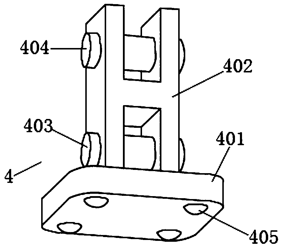
[0027] Among them such as Figure 2-3 As shown, the guide bearing block 4 is slidably installed on the upper surface of the abutment 1; the guide bearing block 4 includes a bearing plate 401 and a support block 402 in an H-shaped structure; the support block 402 ...

specific Embodiment 2

[0030] The horizontal hydraulic telescopic part 3 includes a plurality of horizontal hydraulic cylinders; a plurality of horizontal hydraulic cylinders are coaxially arranged, and a plurality of horizontal hydraulic cylinders are connected end to end in turn; that is, the output end of one horizontal hydraulic cylinder is connected to another On the end of the cylinder body of the horizontal hydraulic cylinder; other structures are identical to the technical scheme in the specific embodiment one.

specific Embodiment 3

[0032] A mounting block is arranged between the four horizontal hydraulic telescopic parts 3; the mounting block is fixed on the upper surface of the base 1; the upper surface of the mounting block is vertically equipped with a guiding support member for ensuring the lifting platform 2 to move up and down smoothly The guiding support component is a vertical hydraulic cylinder or other mechanisms capable of guiding work; the output end of the vertical hydraulic cylinder is fixed on the lower surface of the lifting platform 2; other structures are the same as the technical solution in the first embodiment.

[0033] For the layout between the hydraulic cylinders of multiple groups of hydraulic linkage lifting mechanisms, in Figure 1-5 In the technical scheme of the present invention, the horizontal hydraulic telescopic part 3 is arranged on the inner side of the inclined hydraulic telescopic part 5, and the included angle between the hydraulic telescopic part 3 and the inclined h...


PUM


Abstract

The invention discloses a multi-group hydraulic linkage lifting mechanism, and relates to the technical field of lifting equipment. The multi-group hydraulic linkage lifting mechanism comprises a baseplatform and a lifting platform that are arranged in parallel; the base platform is arranged below the lifting platform; the upper surface of the base platform is provided with at least three horizontal hydraulic telescopic components along the annular direction; guiding bearing blocks are mounted at the output ends of the horizontal hydraulic telescopic components; inclined hydraulic telescopiccomponents are rotationally mounted at the upper parts of the guiding bearing blocks; and the upper end parts of the inclined hydraulic telescopic components are rotationally mounted on the lower surface of the lifting platform. By designing of the multi-group hydraulic linkage lifting mechanisms, the horizontal hydraulic telescopic components are connected with the inclined hydraulic telescopic components by using the guiding bearing blocks, so as to realize the large-scale up and down movement of the lifting platform and effectively improve the lifting effect, and therefore, the multi-grouphydraulic linkage lifting mechanism has relatively high market application value.

Description

technical field [0001] The invention belongs to the technical field of lifting equipment, in particular to a multi-group hydraulic linkage lifting mechanism. Background technique [0002] Car lift refers to the car maintenance equipment used for car lifting in the car maintenance industry. Lifts play a vital role in vehicle maintenance and maintenance. No matter whether the vehicle is overhauled or minor repairs, it is inseparable from it. The nature and quality of its products directly affect the personal safety of maintenance personnel. In the repair and maintenance enterprises of different sizes, whether it is a comprehensive repair shop that repairs a variety of models, or a street shop with a single business scope, almost all of them are equipped with lifts. [0003] The State Intellectual Property Office of the People's Republic of China published a patent document with the authorized announcement number CN107324244B on July 02, 2019. The name is a four-column lift ba...

Claims


Application Information

Patent Timeline
Patent Type & Authority Applications(China)
IPC IPC(8): B66F7/20B66F7/28
CPCB66F7/20B66F7/28
Inventor 潘李林
Owner 界首市神机合自动化科技有限公司
Why Eureka
Try Eureka