Optical structure and method for shortening RGB light mixing distance

A light mixing distance and optical structure technology, applied to optical elements, optics, optical elements, etc. used to change the spectral characteristics of emitted light, can solve insufficient RGB color mixing, variegated colors on the light exit surface, and limited light mixing distance and other problems, to achieve the effect of uniform light mixing, simple structure and convenient use

Pending Publication Date: 2020-07-03
CHANGZHOU XINGYU AUTOMOTIVE LIGHTING SYST
0 Cites 0 Cited by

AI-Extracted Technical Summary

Problems solved by technology

However, since the size of most ambient lights is limited by the A surface of the car body, the distance that can be reserved for light mixing is often very limit...

Method used

According to an embodiment of the present invention, reflective support 40 is formed as white support or aluminum plated support, and thickness is 2mm-5mm, can improve reflection efficiency, reach better reflection effect, reduce light loss, make mixed light brighter .
According to one embodiment of the present invention, light entrance surface 33 and corresponding RGB light source 20 are parallel to each other, RGB light source is fixed on one side of light guide plate 30 by PCB board 10, and the light that RGB light source 20 sends can be taken in parallel. The glossy surface 33 can reduce the loss of light and improve the brightness of mixed light.
As shown in Figure 3, according to an embodiment of the present invention, the optical structure 100 that shortens the RGB light mixing distance can also comprise reflective support 40, and reflective support 40 can be located at the side of light guide plate 30, and reflective support 40 can Allowing at least a part of the light refracted from the light guide plate 30 to return to the light guide plate 30 can reduce light loss, improve the utilization rate of light, and increase the brightness of mixed light.
Further, the light guide plate 30 is also provided with a diffuse reflection part 35, and the diffuse reflection part 35 is located on the side where the light mixing part 32 is located at the back of the light guide bar 31. The method also includes: S3, placing the light mixing part 32 The mixed light is guided to the diffuse reflection part 35 and emitted from the diffuse reflection part 35, so that the mixed light can be mixed twice, and the sufficient degree of mixing of various monochromatic lights can be further improved.
In a word, the optical structure 100 that shortens the RGB light mixing distance according to the embodiment of the present invention adopts the structure that the PCB board 10, a plurality of RGB light sources 20 and the light guide plate 30 combine, and at least two RGB light sources 20 are located on the PCB board 10, at least two light guide strips 31 in the light guide plate 30 are arranged opposite to the RGB light source 20, and the light emitted by each RGB light source 20 can enter the corresponding light guide strip 31 and be reflected by the side reflective surface 34 Afterwards, the light is emitted to the same light mixing part 32 for mixing processing, and the mixed light then enters the diffuse reflection part 35 and is emitted from the light exit surface 36 after multiple reflections. This structure can not only shorten the mixing distance of the RGB light source 20 and improve the uniformity of light mixing, but also has the advantages of simple structure and convenient use.
In other words, the optical structure 100 that shortens the RGB light mixing distance according to the embodiment of the present invention is mainly made up of PCB board 10, a plurality of RGB light sources 20 and light guide plate 30, and two or more than two RGB light sources 20 can be located at respectively On one side of the PCB board 10, the light guide plate 30 may include a plurality of light guide strips 31 and a light mixing part 32, and the plurality of light guide strips 31 may be distributed at intervals, and each light guide strip 31 may correspond to each RGB light source 20 , can maximize the amount of light received by the light guide strip 31 , and each light guide strip 31 can be provided with a light entrance surface 33 and a side reflection surface 34 . That is to say, the light emitted by each RGB light source 20 can first enter the light entrance surface 33 of the corresponding light guide strip 31, and then can be reflected by the side reflection surface 34 of the corresponding light guide strip 31 to perform light mixing once. A light mixing part 32 is provided in the direction where the light guide bar 31 faces away from the light source 20, and the light mixing part 32 can be connected to the side reflection surface 34 corresponding to each light guide bar 31, that is to say, the light entering each light guide bar 31 After being reflected by the corresponding side reflective surface 34 , it can enter the same light mixing portion 32 for secondary mixing of light.
It should be noted that, taking the automotive interior ambient light as an example, a plurality of light sources 20 can be RGB light sources 20 respectively, and the RGB light sources 20 and the PCB board 10 can be formed into RGB modules, and one end of the PCB board 10 can be connected with the light guide The plates 30 are connected, and each light-incoming surface 33 can be kept parallel to each corresponding RGB light source 20 , so that the light utilization rate of the entire light guide plate 30 can be improved to the greatest extent. For example, each RGB light source can be composed of three-color LED light sources, which can meet the requirements for the color of light. According to the optical structure 100 of the embodiment of the present invention, the three monochromatic lights emitted by each RGB three-color chip will be reflected multiple times inside the strip light guide structure (light guide bar 31) of the light mixing part, so that the three Monochromatic light is more fully mixed into 30 different colors of mixed light, and the angle of mixed light will become smaller. The mixed light with a smaller angle is reflected again by the spherical structure (optical pattern structure) behind the light guide plate 30 and then emitted from the light exit surface 36, so that the length of the entire mixed light area can be shortened by 5 mm to 10 mm, providing a certain space for the structure of the lamp, and at the same time It can achieve the effect of increasing the light emitting surface.
Optionally, the optical pattern is formed as a spherical or conical spaced on the light-emitting surface 36, the optical pattern is a concave pattern or a convex pattern, and the diameter of the spherical or conical structure can be 0.15mm-0.65mm, which can be Prevent the total reflection of the mixed light at the diffuse reflection part 35, and reflect the light to the outside of the light-emitting surface, so that the light guide plate 30 can emit bright light as a whole, which is convenient for production and processing, and can also make the mixed light emitted by the light-emitting surface 36 more uniform.
Optionally, the spacing between two adjacent light guide strips 31 can be 1.5mm-2.5mm, and the length of each light guide strip 31 can be 10mm-15mm, which can achieve better light mixing effect and shorten RGB Light mixing distance. The light guide plate 30 may be formed as a transparent member, and its thickness may be 2mm-5mm.
Specifically, a plurality of RGB light sources 20 are set at intervals on one side of the PCB board 10, and the light guide plate 30 is arrang...

Abstract

The invention discloses an optical structure and method for shortening the RGB light mixing distance. The optical structure comprises a PCB; a plurality of RGB light sources which are arranged on oneside of the PCB at intervals; a light guide plate which is arranged on one side of the PCB; a light guide plate which includes a plurality of light sources which are distributed at intervals and correspond to the plurality of RGB light sources respectively, wherein each light guide strip is in a long strip shape, the end face, opposite to the RGB light source, of each light guide strip forms a light inlet face, the side face of each light guide strip forms a side reflection face, and light emitted by each RGB light source passes through the corresponding light inlet face and then is reflectedby the side reflection face multiple times to reduce the reflection angle of the light; and a light mixing part, wherein one end of the light mixing part is connected with the other ends of the plurality of light guide strips, and the light mixed by the plurality of light guide strips enters the light mixing part for secondary light mixing. According to the optical structure capable of shorteningthe RGB light mixing distance, light entering the light incoming surface is reflected multiple times through the light guide plate and then mixed, the RGB light mixing distance can be shortened, and the optical structure has the advantages of being simple in structure, convenient to use and the like.

Application Domain

Mechanical apparatusVehicle interior lighting +6

Technology Topic

EngineeringLight guide +1

Image

  • Optical structure and method for shortening RGB light mixing distance
  • Optical structure and method for shortening RGB light mixing distance
  • Optical structure and method for shortening RGB light mixing distance

Examples

  • Experimental program(1)

Example Embodiment

[0029] The embodiments of the present invention are described in detail below. Examples of the embodiments are shown in the accompanying drawings, in which the same or similar reference numerals indicate the same or similar elements or elements with the same or similar functions. The embodiments described below with reference to the drawings are exemplary, and are only used to explain the present invention, but should not be understood as limiting the present invention.
[0030] In the description of the present invention, it should be understood that the terms "center", "longitudinal", "transverse", "length", "width", "thickness", "upper", "lower", "front", " Back", "Left", "Right", "Vertical", "Horizontal", "Top", "Bottom", "Inner", "Outer", "Clockwise", "Counterclockwise", "Axial", The orientation or positional relationship indicated by "radial", "circumferential", etc. is based on the orientation or positional relationship shown in the drawings, and is only for the convenience of describing the present invention and simplifying the description, rather than indicating or implying the pointed device or element It must have a specific orientation, be constructed and operated in a specific orientation, and therefore cannot be understood as a limitation of the present invention. In addition, the features defined with "first" and "second" may explicitly or implicitly include one or more of these features. In the description of the present invention, unless otherwise specified, "plurality" means two or more.
[0031] In the description of the present invention, it should be noted that the terms "installation", "connected" and "connected" should be understood in a broad sense, unless otherwise clearly specified and limited. For example, they can be fixed or detachable. Connected or integrally connected; it can be a mechanical connection or an electrical connection; it can be directly connected or indirectly connected through an intermediate medium, and it can be the internal communication between two components. For those of ordinary skill in the art, the specific meanings of the above-mentioned terms in the present invention can be understood in specific situations.
[0032] Hereinafter, the optical structure 100 for shortening the RGB mixing distance according to the embodiment of the present invention will be described in detail with reference to the accompanying drawings.
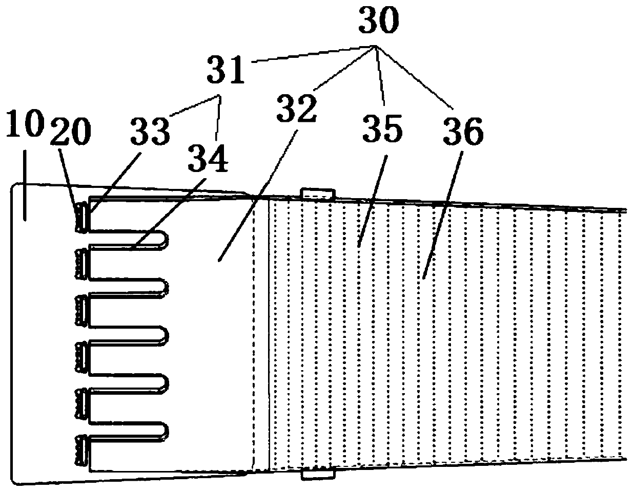
[0033] Such as Figure 1 to Figure 3 As shown, the optical structure 100 for shortening the RGB mixing distance according to the embodiment of the present invention includes a PCB board 10, a plurality of RGB light sources 20 and a light guide plate 30.
[0034] Specifically, a plurality of RGB light sources 20 are arranged at intervals on one side of the PCB board 10, and the light guide plate 30 is arranged on one side of the PCB board 10. The light guide plate 30 includes a plurality of light guide bars 31 and a light mixing portion 32, The light bars 31 are spaced apart and correspond to a plurality of RGB light sources 20. Each light guide bar 31 is formed in a long strip shape and the end face opposite to the RGB light source 20 is formed as a light entrance surface 33. Each light guide bar 31 The side surface of each RGB light source 20 is formed as a side reflective surface 34, and the light emitted by each RGB light source 20 is respectively reflected by the side reflective surface 34 after passing through the corresponding light entrance surface 33 to reduce the reflection angle of the light. The other ends of the plurality of light guide strips 31 are connected, and the light mixed by the plurality of light guide strips 31 enters the light mixing part 32 for secondary light mixing.
[0035] In other words, the optical structure 100 for shortening the RGB mixing distance according to the embodiment of the present invention is mainly composed of a PCB board 10, a plurality of RGB light sources 20 and a light guide plate 30, and two or more RGB light sources 20 can be respectively arranged on the PCB board 10. On one side of the light guide plate 30, the light guide plate 30 may include a plurality of light guide strips 31 and a light mixing part 32. The plurality of light guide strips 31 can be spaced apart and distributed. Each light guide strip 31 can correspond to each RGB light source 20, which can be the largest The quantity of light received by the light guide strip 31 is increased to a certain extent, and each light guide strip 31 may be provided with a light entrance surface 33 and a side reflection surface 34. That is to say, the light emitted by each RGB light source 20 can first enter the light entrance surface 33 of the corresponding light guide strip 31, and then can be reflected by the side reflection surface 34 of the corresponding light guide strip 31 for a single mixing. A light mixing part 32 is provided in the direction of the light guide strip 31 away from the light source 20, and the light mixing part 32 can be connected with the side reflection surface 34 corresponding to each light guide strip 31, that is, the light entering each light guide strip 31 After being reflected by the corresponding side reflecting surface 34, it can enter the same light mixing part 32 for secondary mixing of light.
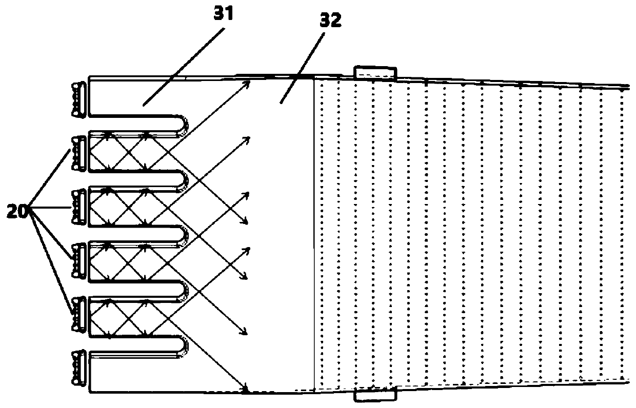
[0036] It should be noted that the light emitted by the RGB light source 20 is guided to the light guide strip 31 and then undergoes multiple total reflections therein, that is, the angle becomes smaller after being reflected by the side reflection surface on the light guide part 31, which can increase The number of reflections increases the mixing rate and the degree of light fusion, thereby shortening the length of the entire light mixing part, and also making the light mixing more uniform.
[0037] Therefore, according to the optical structure 100 for shortening the RGB mixing distance according to the embodiment of the present invention, the PCB board 10, the multiple RGB light sources 20 and the light guide plate 30 are combined to form the multiple RGB light sources 20 on the PCB board 10. On one side, at least two light guide strips 31 in the light guide plate 30 are arranged opposite to the RGB light source 20, and the light emitted by each RGB light source 20 can enter the corresponding light guide strip 31, and can be emitted after being reflected by the side reflecting surface 34 To the light mixing part 32 for mixing processing, this structure can not only shorten the mixing distance of light of different colors, make the light mixing more uniform, but also has the advantages of simple structure and convenient use.
[0038] According to an embodiment of the present invention, the light entrance surface 33 and the corresponding RGB light source 20 are parallel to each other, the RGB light source is fixed on one side of the light guide plate 30 through the PCB board 10, and the light emitted by the RGB light source 20 can be parallelly taken into the light entrance surface 33 , Can reduce the loss of light and improve the brightness of mixed light.
[0039] Optionally, the light guide plate 30 may further include a diffuse reflection part 35, which may be provided at the other end of the light mixing part 32, and one end of the diffuse reflection part 35 may be connected to the light mixing part 32. The side surface is formed as a light-emitting surface provided with an optical pattern structure. The light that has passed through the light mixing portion 32 for secondary mixing is reflected by the optical pattern structure to the outside of the light-emitting surface 36, that is, the diffuse reflection portion 35 can mix the light of the mixing portion 32 After performing multiple reflections, the light is reflected to the light-emitting surface 36, so that the mixed light emitted by the light-emitting surface 36 can be more uniform and bright. That is to say, the light emitted by the multiple RGB light sources 20 is separately reflected by the multiple light guide strips 31, and then passes through the light mixing section 32 for secondary mixing, which can make the light mixing more uniform and reduce noise.
[0040] In some specific embodiments of the present invention, the diffuse reflection portion 35 may also be formed as a tooth-shaped optical pattern structure, and a uniform lighting effect can be achieved by adjusting the size and density distribution of the optical pattern structure.
[0041] Optionally, the optical pattern is formed into a spherical or conical shape spaced on the light exit surface 36, the optical pattern is a concave or convex pattern, and the diameter of the sphere or conical structure can be 0.15mm-0.65mm, which can prevent mixed light. Total reflection occurs at the diffuse reflection part 35 to reflect the light to the outside of the light exit surface, so that the light guide plate 30 can emit bright light as a whole, which is convenient for production and processing, and can also make the mixed light emitted by the light exit surface 36 more uniform.
[0042] Preferably, two adjacent light guide strips 31 are parallel to each other, so as to ensure that the light in each light guide strip 31 has the same reflection angle, and it is convenient to mix the light emitted by the multiple RGB light sources 20 to the best effect.
[0043] According to an embodiment of the present invention, each light guide strip 31 is formed as a long light guide channel, and one end of the long light guide channel is formed as a light entrance surface 33. It should be noted that the light entrance surface 33 may be a virtual The surface may be formed as a light inlet communicating with the light guide channel, for example. The light emitted by each RGB light source 20 can enter from one end of the corresponding long light guide channel. The inner wall surface of each long light guide channel is formed as a side reflective surface 34, and the side reflective surface 34 can enter into it. The light of the corresponding light entrance surface 33 is reflected, such as figure 2 As shown, the arrow direction in the figure represents a schematic diagram of light reflecting on the inner wall surface of the long light guide channel. From figure 2 It can be seen that by providing multiple light guide strips 31, the number of total reflections of light on the side reflection surface 34 can be increased, the reflection angle can be reduced, and the effect of shortening the RGB mixing distance can be achieved. A light mixing part 32 may be provided at the other end of the light guide strip 31 along its length. The light mixing part 32 may be formed with a light mixing channel connected to each light guide strip 31, passing through each light guide strip. 31 reflected light can enter the mixing channel for mixing. By maintaining the consistency of the width and length of the plurality of strip-shaped light guide structures (light guide strips 31), the light emitted by each RGB light source 20 maintains the same reflection angle, thereby improving the uniformity of the light mixing part. So as to achieve the best mixing effect.
[0044] Optionally, the distance between two adjacent light guide strips 31 can be 1.5mm-2.5mm, and the length of each light guide strip 31 can be 10mm-15mm, which can achieve better light mixing effect and shorten the RGB mixing distance . The light guide plate 30 may be formed as a transparent member, and its thickness may be 2mm-5mm.
[0045] Such as image 3 As shown, according to an embodiment of the present invention, the optical structure 100 for shortening the RGB mixing distance may further include a reflective bracket 40. The reflective bracket 40 may be provided on one side of the light guide plate 30. The light refracted in 30 returns to the light guide plate 30, which can reduce light loss, increase the utilization rate of light, and improve the brightness of mixed light.
[0046] According to an embodiment of the present invention, the reflective bracket 40 is formed as a white bracket or an aluminum-plated bracket with a thickness of 2mm-5mm, which can improve the reflection efficiency, achieve a better reflection effect, reduce light loss, and make the mixed light brighter.
[0047] It should be noted that taking the automotive interior atmosphere lamp as an example, the multiple light sources 20 may be RGB light sources 20, respectively, the RGB light sources 20 and the PCB board 10 may be formed as RGB modules, and one end of the PCB board 10 may be connected to the light guide plate 30 Each light entrance surface 33 can be kept parallel to each corresponding RGB light source 20, so that the light utilization rate of the entire light guide plate 30 can be maximized. For example, each RGB light source can be composed of three-color LED light sources, which can meet the requirements for the color of light. According to the optical structure 100 of the embodiment of the present invention, the three monochromatic lights emitted by each RGB three-color chip will be reflected multiple times inside the strip light guide structure (light guide strip 31) of the light mixing part, so that three The monochromatic light is more fully mixed into 30 different colors of mixed light, and the angle of the mixed light will become smaller. The mixed light whose angle becomes smaller is reflected again by the spherical structure (optical pattern structure) behind the light guide plate 30 and then emitted from the light-emitting surface 36, so that the length of the entire light-mixing area can be shortened by 5mm to 10mm, which provides a certain space for the structure of the lamp. The effect of increasing the light-emitting surface can be achieved.
[0048] The method for shortening the RGB mixing distance according to the embodiment of the present invention includes the following steps: S1, multiple RGB light sources 20 are installed on the PCB board 10; S2, a light guide plate 30 is provided on one side of the RGB light source 20, and the light guide plate 30 is provided On one side of the RGB light source 20, the light guide plate 30 is formed in a long strip shape. A plurality of light guide bars and a light mixing section 32 are sequentially arranged along the length of the light guide plate 30. The width direction is spaced apart. The multiple light guide strips 31 respectively correspond to the multiple RGB light sources 20, and the light emitted by each RGB light source 20 can be totally reflected by the corresponding light guide strip 31 to reduce the reflection angle of the light. The light reflected by the strip 31 enters the light mixing part 32 and is mixed. That is to say, the light guide strip 31 and the mixing part 32 can be sequentially arranged on the light guide plate 30 from left to right, the RGB light source 20 is arranged on the left side of the light guide strip 31, and the light emitted by the multiple RGB light sources 20 are respectively guided To the corresponding light guide strip 31, after multiple reflections in the corresponding light guide strip 31, the reflection angle of the light can be reduced, thereby shortening the light mixing length.
[0049] Further, the light guide plate 30 is further provided with a diffuse reflection portion 35, which is provided on the side of the light mixing portion 32 facing away from the position where the light guide bar 31 is located, and the method further includes: S3, mixing the light mixing portion 32 The light is guided to the diffuse reflection part 35 and emitted from the diffuse reflection part 35, so that the mixed light can be subjected to secondary mixing, and the sufficient degree of mixing of multiple monochromatic lights can be further improved.
[0050] In a word, the optical structure 100 for shortening the RGB mixing distance according to the embodiment of the present invention adopts the structure of the PCB board 10, the multiple RGB light sources 20 and the light guide plate 30, and at least two RGB light sources 20 are arranged on one of the PCB boards 10. On the side, at least two light guide strips 31 in the light guide plate 30 are arranged opposite to the RGB light source 20, and the light emitted by each RGB light source 20 can enter the corresponding light guide strip 31, and can be reflected by the side reflecting surface 34 and emitted to The same light mixing part 32 is used for mixing processing, and the mixed light enters the diffuse reflection part 35 and exits the light exit surface 36 after being reflected multiple times. This structure can not only shorten the mixing distance of the RGB light source 20 and improve the uniformity of light mixing, but also has the advantages of simple structure and convenient use.
[0051] In the description of this specification, the description with reference to the terms "one embodiment", "some embodiments", "exemplary embodiments", "examples", "specific examples", or "some examples" etc. means to incorporate the implementation The specific features, structures, materials or characteristics described by the examples or examples are included in at least one embodiment or example of the present invention. In this specification, the schematic representation of the above-mentioned terms does not necessarily refer to the same embodiment or example. Moreover, the described specific features, structures, materials or characteristics may be combined in any one or more embodiments or examples in a suitable manner.
[0052] Although the embodiments of the present invention have been shown and described, those of ordinary skill in the art can understand that various changes, modifications, substitutions, and modifications can be made to these embodiments without departing from the principle and purpose of the present invention. The scope of the present invention is defined by the claims and their equivalents.

PUM

PropertyMeasurementUnit
Length10.0 ~ 15.0mm

Description & Claims & Application Information

We can also present the details of the Description, Claims and Application information to help users get a comprehensive understanding of the technical details of the patent, such as background art, summary of invention, brief description of drawings, description of embodiments, and other original content. On the other hand, users can also determine the specific scope of protection of the technology through the list of claims; as well as understand the changes in the life cycle of the technology with the presentation of the patent timeline. Login to view more.

Similar technology patents

LED backlight module

ActiveCN101571264AShorten the mixing distanceReduce the amount used
Owner:SHANGHAI AVIC OPTOELECTRONICS

Structure of small-sized refraction astigmatism lens and backlight module

PendingCN107807474AShorten the mixing distancereduce distance
Owner:SHENGLAN TECH CO LTD

Backlight module, display device and manufacturing method of backlight module

InactiveCN108732818AIncrease the light output angleShorten the mixing distance
Owner:WUHAN CHINA STAR OPTOELECTRONICS TECH CO LTD

Low space color cast LED packaging structure

ActiveCN103367609AReduce spatial color castEvenly mixed light
Owner:NAT CENT UNIV

Straight-down type backlight source structure, backlight source module and liquid crystal display device

ActiveCN104110612AShorten the mixing distancereduce product cost
Owner:CHONGQING BOE DISPLAY LIGHTING CO LTD +1

Classification and recommendation of technical efficacy words

  • shorten the mixing distance
  • Evenly mixed light

LED backlight module

ActiveCN101571264AShorten the mixing distanceReduce the amount used
Owner:SHANGHAI AVIC OPTOELECTRONICS

Backlight module, display device and manufacturing method of backlight module

InactiveCN108732818AIncrease the light output angleShorten the mixing distance
Owner:WUHAN CHINA STAR OPTOELECTRONICS TECH CO LTD

Straight-down type backlight source structure, backlight source module and liquid crystal display device

ActiveCN104110612AShorten the mixing distancereduce product cost
Owner:CHONGQING BOE DISPLAY LIGHTING CO LTD +1

Structure of small-sized refraction astigmatism lens and backlight module

PendingCN107807474AShorten the mixing distancereduce distance
Owner:SHENGLAN TECH CO LTD

Low space color cast LED packaging structure

ActiveCN103367609AReduce spatial color castEvenly mixed light
Owner:NAT CENT UNIV
Why Eureka
Try Eureka