Backlight module and display apparatus

a backlight module and display apparatus technology, applied in the field of backlight modules and display apparatuses, can solve the problems of poor color performance and narrow color gamut, difficult to achieve real color of images, and high energy consumption of light sources of backlight modules, so as to reduce the energy consumption of light sources, improve the display quality, and wide color gamut

Active Publication Date: 2014-05-08
SHENZHEN CHINA STAR OPTOELECTRONICS TECH CO LTD
View PDF3 Cites 10 Cited by
  • Summary
  • Abstract
  • Description
  • Claims
  • Application Information

AI Technical Summary

Benefits of technology

[0016]In comparison to the problems existing in the conventional backlight module, the backlight module and the display apparatus of the present invention can use the ambient light rays to form the backlight source, thereby greatly reducing an energy consumption of light sources. Moreover, the ambient light can have a wide color gamut, and thus the display apparatus using the backlight module of the present invention can display images of real color for improving a display quality thereof. Furthermore, with the use of the light diffusion recessions of the light guide plate, the light rays transmitted by the optical fibers can be laterally diffused for mixing light, thereby reducing the light mixing distance thereof, as well as solving the hotspot problem occurring at the light-incident side of the light guide plate.

Problems solved by technology

In general, light sources of the backlight module are light emitting diodes (LEDs) or cold cathode fluorescent lamps (CCFLs) which need phosphors to form white light rays which have a poorer color performance and a narrower color gamut, and thus it is difficult to achieve a real color of images.
Furthermore, the light sources of the backlight module have a high energy consumption, especially for a large-size LCD.

Method used


Image

  • Backlight module and display apparatus
  • Backlight module and display apparatus
  • Backlight module and display apparatus

Examples


Embodiment Construction

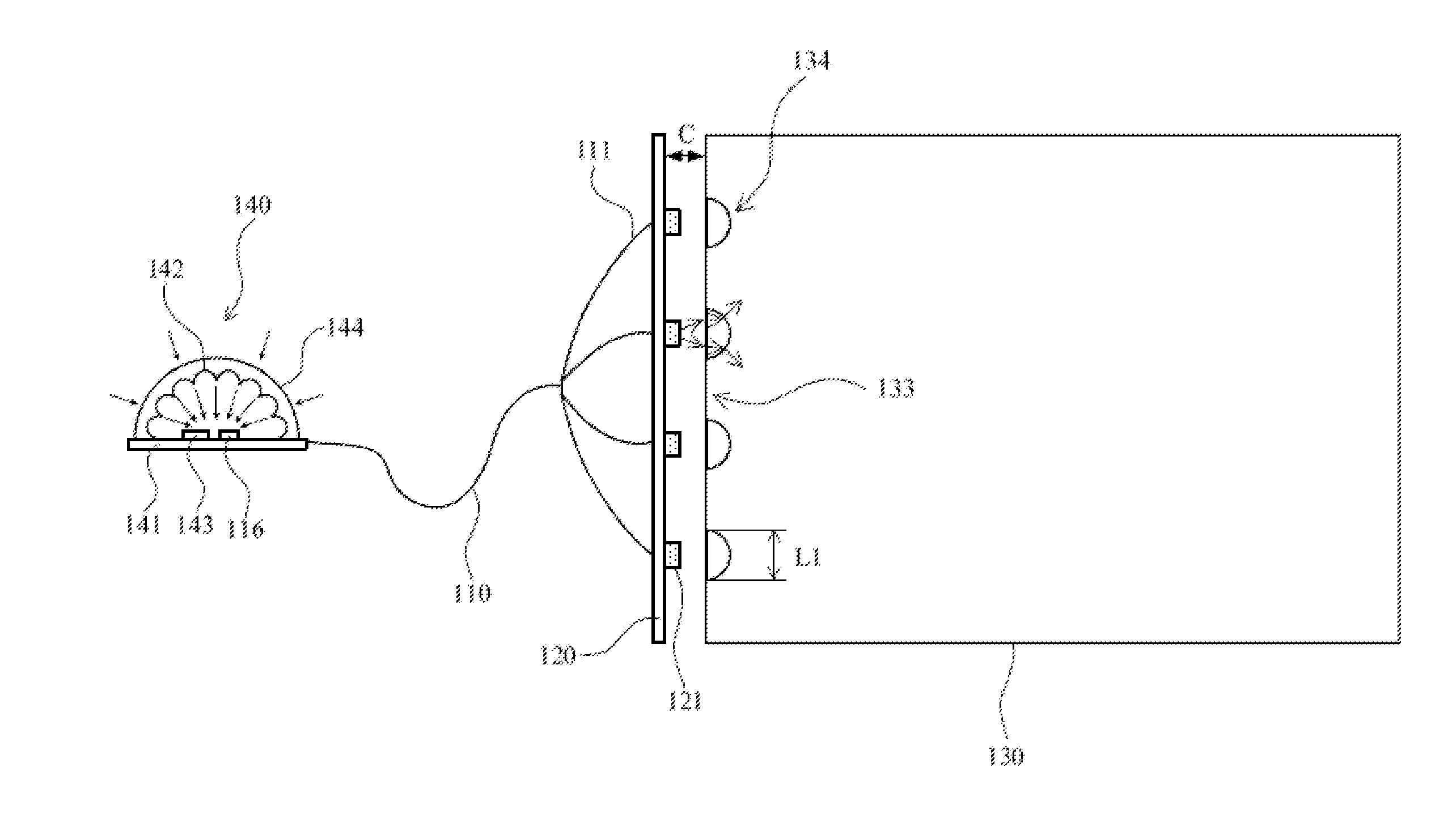
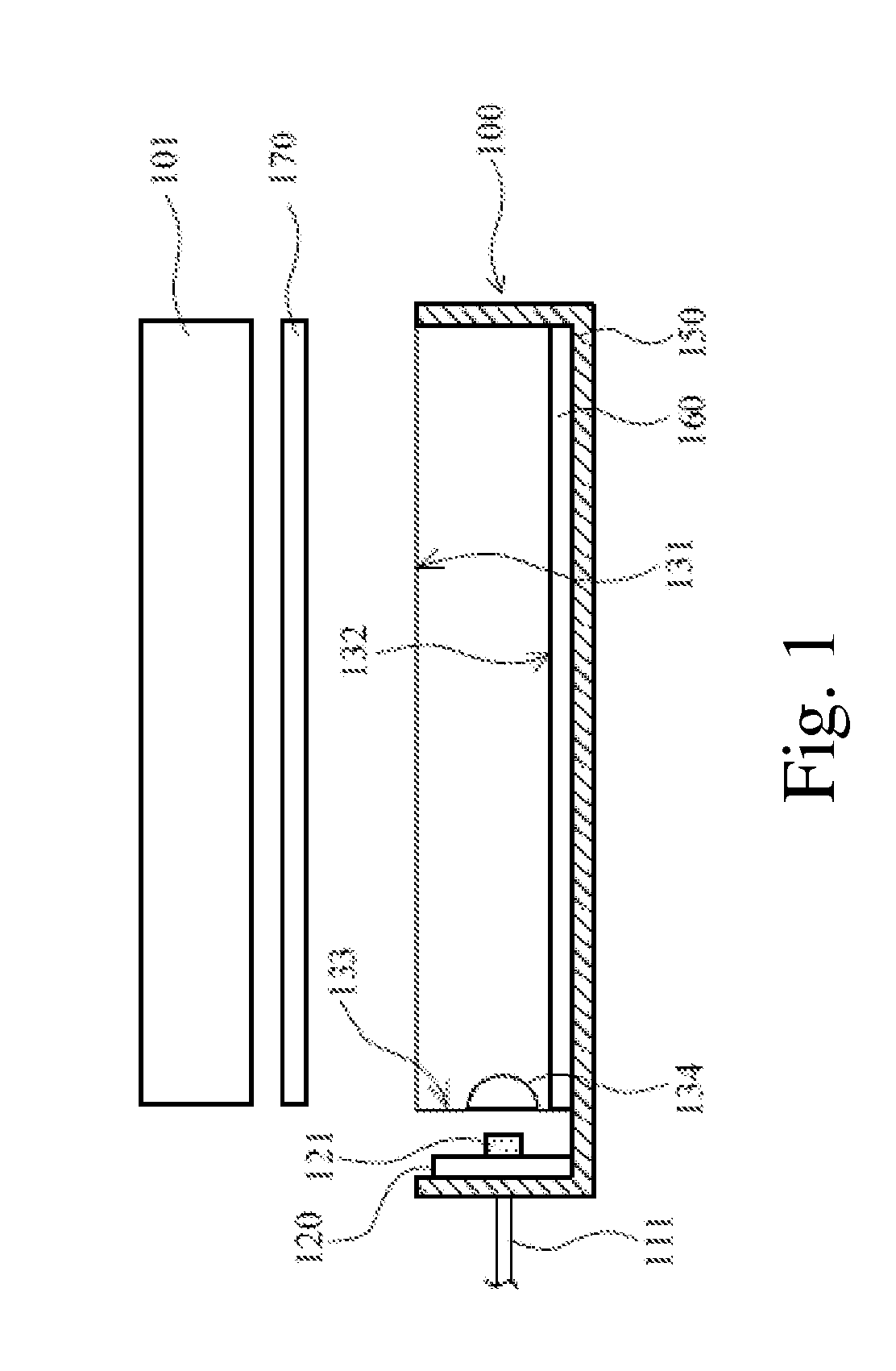
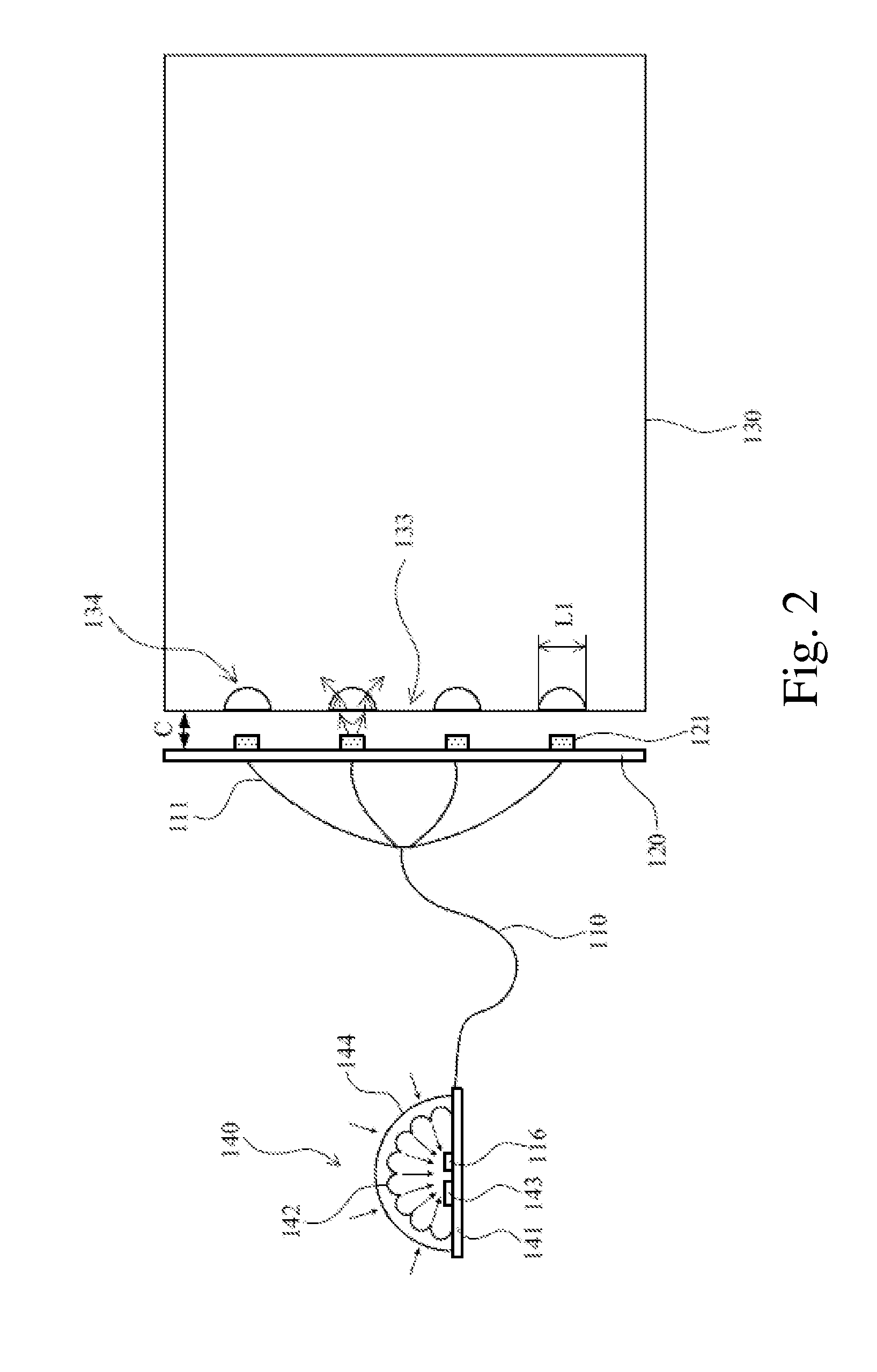
[0024]The following embodiments are referring to the accompanying drawings for exemplifying specific implementable embodiments of the present invention. Furthermore, directional terms described by the present invention, such as upper, lower, front, back, left, right, inner, outer, side and etc., are only directions by referring to the accompanying drawings, and thus the used directional terms are used to describe and understand the present invention, but the present invention is not limited thereto.

[0025]The drawings and description are to be regarded as illustrative in nature and not restrictive. Like reference numerals designate like elements throughout the specification. In addition, the size and thickness of each component shown in the drawings are arbitrarily shown for understanding and ease of description, but the present invention is not limited thereto.

[0026]In the drawings, the thickness of layers, films, panels, regions, etc., are exaggerated for clarity. In the drawings, ...


PUM


Abstract

The present invention provides a backlight module and a display apparatus. The display apparatus comprises the backlight module and a display panel. The backlight module comprises a light collector, optical fibers, a fiber light-outputting substrate and a light guide plate. The optical fibers are connected between the light collector and the fiber light-outputting substrate. The light guide plate is disposed at one side of the fiber light-outputting substrate. The light guide plate includes light diffusion recessions, and the light diffusion recessions face the light-outputting openings of the fiber light-outputting substrate. The present invention can use ambient light rays to form a backlight source.

Description

FIELD OF THE INVENTION[0001]The present invention relates to a backlight module and a display apparatus, and more particularly to a backlight module and a display apparatus using ambient light rays.BACKGROUND OF THE INVENTION[0002]Liquid crystal displays (LCDs) have been widely applied in electrical products. Currently, most LCDs are backlight type LCDs that comprise a liquid crystal display panel and a backlight module. According to the position of the light sources for providing LCDs with backlight, the backlight module can be classified into a side-light type or a direct-light type to provide a backlight for the liquid crystal display panel.[0003]In general, light sources of the backlight module are light emitting diodes (LEDs) or cold cathode fluorescent lamps (CCFLs) which need phosphors to form white light rays which have a poorer color performance and a narrower color gamut, and thus it is difficult to achieve a real color of images. Furthermore, the light sources of the back...

Claims


Application Information

Patent Timeline
Patent Type & Authority Applications(United States)
IPC IPC(8): F21V8/00
CPCG02B6/0016G02B6/001G02B6/002G02B6/0028
Inventor HU, CHECHANGHE, HU
Owner SHENZHEN CHINA STAR OPTOELECTRONICS TECH CO LTD
Why Eureka
Try Eureka