Backlight module

A backlight module and backside technology, applied in the direction of optics, light guides, optical components, etc., can solve the problems of dark corners of liquid crystal panels, increasing the thickness and volume of liquid crystal display backlight modules, limitations, etc.

Inactive Publication Date: 2004-12-29
AU OPTRONICS CORP
View PDF0 Cites 9 Cited by
  • Summary
  • Abstract
  • Description
  • Claims
  • Application Information

AI Technical Summary

Problems solved by technology

Therefore, the arrangement of light emitting diodes limits the length of the light mixing distance, and a longer light mixing distance increases the thickness and volume of the LCD backlight module
In addition, in the direct-lit backlight module, due to the light characteristics and the arrangement of the light-emitting diodes, the corners of the LCD panel are dark and other problems.

Method used


Image

  • Backlight module
  • Backlight module
  • Backlight module

Examples


Embodiment Construction

[0013] In order to make the above-mentioned objects, features and advantages of the present invention more comprehensible, a preferred embodiment is given below and described in detail with accompanying drawings.

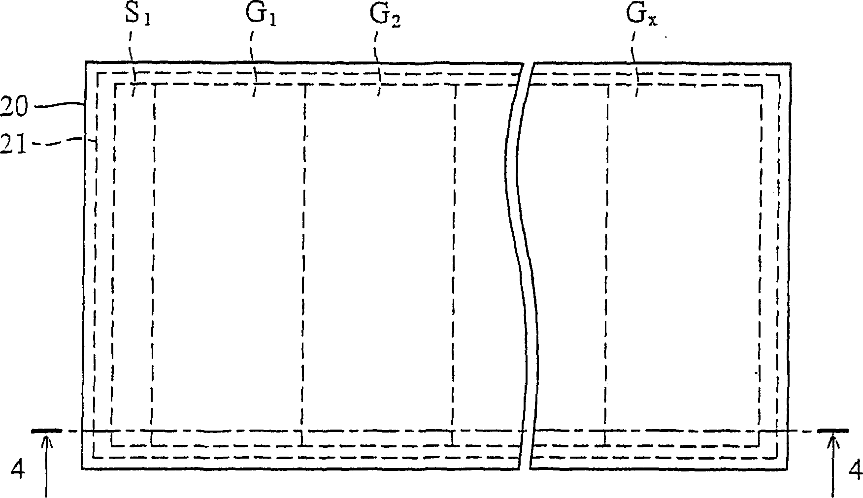
[0014] image 3 It is a schematic plan view showing the direct type backlight module of the liquid crystal display of the present invention. Figure 4 express image 3 A schematic cross-sectional view along the tangent line 4-4 in . The backlight light source of the present invention uses red, green and blue light-emitting diodes to mix into white light to provide to the liquid crystal panel. refer to image 3 and Figure 4 , the direct type backlight module of the present invention has a diffusion plate 20, an outer frame 21, a light guide plate G 1 to G x , Shade S 1 to S x and multiple light emitting diodes. A space 23 is formed between the outer frame 21 and the diffusion plate 20, and the light guide plate G 1 to G x , Shade board S 1 to S x And a ...


PUM


Abstract

A backlight module. The backlight module includes a diffuser plate, a first light guide plate, a second light guide plate, a plurality of first light sources, and a plurality of second light sources. The first light sources are disposed adjacent to the first light guide plate and emit light through the first guide plate to the diffuser plate. The second light sources are disposed adjacent to the second light guide plate and emit light through the second light guide plate to the diffuser.

Description

technical field [0001] The invention relates to a backlight module, in particular to a backlight module, which is suitable for a direct type liquid crystal display, and uses a light guide plate to mix light sources of different colors to shorten the light mixing distance. Background technique [0002] figure 1 It is a schematic top view showing a conventional direct-lit backlight module of a liquid crystal display. Among them, the light source of the existing direct-type backlight module uses red, green, and blue light-emitting diodes as the light source, and the red, green, and blue light emitted by the red, green, and blue light-emitting diodes are mixed. Produces white light. like figure 1 As shown, there are multiple light emitting diodes L between the outer frame 11 and the diffusion module 10 11 to L nm , where the LED L 11 , L 12 to L 1m placed on the first row, the LED L 21 , L 22 to L 2m placed on the second row, and the LED L n1 , L n2 to L nm placed ...

Claims


Application Information

Patent Timeline
Patent Type & Authority Applications(China)
IPC IPC(8): F21V8/00G01D11/28G02F1/133G02F1/1335G02F1/13357G09G3/36
CPCG02B6/0046G02F1/133609G02F1/133603G02F2001/133607G02B6/0078G02F1/133607
Inventor 高克嘉周信宏
Owner AU OPTRONICS CORP
Why Eureka
Try Eureka