Shift register unit and control method thereof, gate drive circuit and display device

A technology for shifting register units and gates, applied in information storage, static memory, static indicators, etc., can solve problems such as poor visual effects of display devices, affect user visual experience, and increase transistor leakage, and achieve high-quality visual effects , Improve the picture display quality, eliminate the effect of transistor leakage increase

Active Publication Date: 2020-07-03
KUNSHAN GO VISIONOX OPTO ELECTRONICS CO LTD
View PDF12 Cites 4 Cited by
  • Summary
  • Abstract
  • Description
  • Claims
  • Application Information

AI Technical Summary

Problems solved by technology

[0003] However, due to process fluctuations and / or increase in screen temperature, transistor leakage will increase. Therefore, the threshold voltage of the transistor is too high to cause the transistor to be forward-biased, causing the abnormal output of the transistor and causing the flickering problem of the display device, which makes the display device poor visual effect, seriously affecting the user's visual experience

Method used


Image

  • Shift register unit and control method thereof, gate drive circuit and display device
  • Shift register unit and control method thereof, gate drive circuit and display device
  • Shift register unit and control method thereof, gate drive circuit and display device

Examples


Embodiment 1

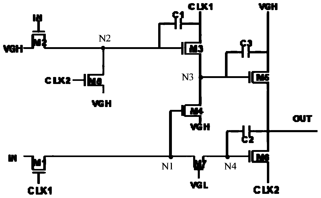
[0068] image 3 It is a schematic structural diagram of a shift register unit provided by an embodiment of the present application. Such as image 3 As shown, the shift register unit of the present application may include:

[0069] The first transistor M1 is controlled by the signal input from the first clock signal terminal CLK1 , and is used for transmitting the signal input from the input signal terminal IN to the first node N1 .

[0070] The second transistor M2 is controlled by the signal input from the input signal terminal IN, and is used for transmitting the signal input from the first voltage signal terminal VGH to the second node N2.

[0071] The third transistor M3 is controlled by the potential signal of the second node N2, and is used for transmitting the signal input from the first clock signal terminal CLK1 to the third node N3.

[0072] The first terminal of the first capacitor C1 is used to input the potential signal of the second node N2, and the second te...

Embodiment 2

[0098] Image 6 It is a schematic structural diagram of a gate driving circuit provided by an embodiment of the present application. Such as Image 6 As shown, the shift register unit of the present application may include:

[0099] The first transistor M1 is controlled by the signal input from the clock signal terminal CLK, and is used for transmitting the signal input from the input signal terminal IN to the first node N1.

[0100] The second transistor M2 is controlled by the signal input from the clock signal terminal CLK, and is used for transmitting the signal input from the first voltage signal terminal VGH to the second node N2.

[0101] The fourth transistor M4 is controlled by the potential signal of the first node N1, and is used for transmitting the signal input from the first voltage signal terminal VGH to the second node N2.

[0102] The fifth transistor M5 is controlled by the potential signal of the second node N2, and is used for transmitting the signal inp...


PUM


Abstract

The invention provides a shift register unit and a control method thereof, a gate drive circuit and a display device. According to the invention, the shift output function of the shift register unit is realized; the high-level output of the shift register unit does not change along with the change of the signal; the stable output of the high level of the shift register is ensured; the phenomenon of transistor electric leakage increase caused by process fluctuation and / or screen body temperature rise is eliminated; the problem of abnormal transistor output caused by increase of transistor electric leakage is solved; according to the shift register, the output stability of the shift register is improved, the problem of splash screen of the display device due to abnormal output of the transistor is avoided, the image display quality of the display device is improved, the actual requirement of a high-quality visual effect is met, and better visual experience is provided for a user.

Description

technical field [0001] The present application relates to the field of display technology, in particular to a shift register unit, a control method thereof, a gate drive circuit and a display device. Background technique [0002] Among active-matrix organic light-emitting diode (AMOLED) panels, organic light-emitting diodes (OLEDs) have been widely used due to their light weight, small size, and low energy consumption. various display devices. [0003] However, due to process fluctuations and / or increase in screen temperature, the leakage of transistors will increase. Therefore, the threshold voltage of the transistors is too high and the transistors are forward-biased, causing abnormal output of the transistors and causing the problem of flickering in the display device, which makes the display device The poor visual effect seriously affects the user's visual experience. Contents of the invention [0004] The present application provides a shift register unit, a control...

Claims


Application Information

Patent Timeline
Patent Type & Authority Applications(China)
IPC IPC(8): G09G3/3266G09G3/20G11C19/28
CPCG09G3/3266G09G3/20G11C19/28G09G2310/0286
Inventor 赵欣朱正勇宋会会胡思明韩珍珍
Owner KUNSHAN GO VISIONOX OPTO ELECTRONICS CO LTD
Why Eureka
Try Eureka