Anti-slip multistage-drop box culvert

An anti-slip and box culvert technology, applied in the field of box culvert structure, can solve the problems of complex box culvert structure, aggravating the construction difficulty of box culvert, unfavorable top soil body of box culvert and the safety and stability of road facilities.

Pending Publication Date: 2020-07-07
中恒工程设计院有限公司
View PDF0 Cites 1 Cited by
  • Summary
  • Abstract
  • Description
  • Claims
  • Application Information

AI Technical Summary

Problems solved by technology

[0003] Installing energy dissipation facilities at the outlet of the box culvert and anti-slip facilities at the bottom of the box culvert not only makes the structure of the box culvert more complicated, but also increases the difficulty of the construction of the box culvert
At the same time, since the top of the traditional box culvert is a relatively smooth slope, when the longitudinal slope of the top of the box culvert is steep, it is easy to cause longitudinal slippage of the covering soil on the top of ...

Method used


Image

  • Anti-slip multistage-drop box culvert
  • Anti-slip multistage-drop box culvert
  • Anti-slip multistage-drop box culvert

Examples


Embodiment 1

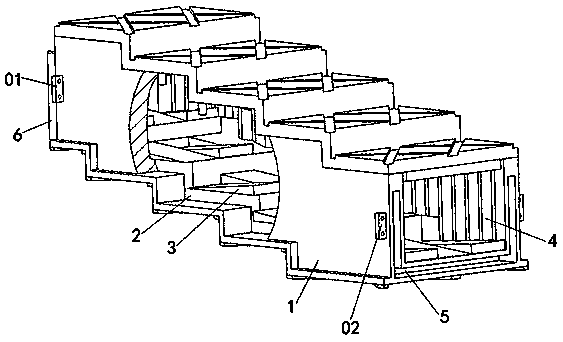
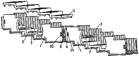
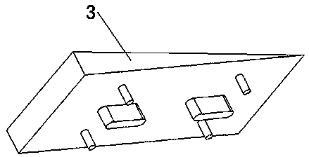
[0039] A kind of anti-slip multi-stage drop water box culvert of this embodiment, such as figure 1 with Figure 4As shown, it includes a hollow box culvert body 1, the outer top and outer bottom of the box culvert body 1 are stepped, and the inner bottom surface of the box culvert body 1 is provided with a number of falling water steps 2 along the direction of water flow. An inclined gentle and steep slope 3 is provided on the step surface of the falling water ladder 2 .

[0040] The outer bottom of the box culvert body 1 is set as a number of continuous steps, each step includes a horizontal step surface and a vertical vertical surface, and the bottom of the steps is provided with a 20cm thick C15 concrete cushion along the step surface and the vertical surface , the steps at the outer bottom of the box culvert body 1 are in contact with the soil through the concrete cushion. The box culvert body 1 is in contact with the soil through the stepped surface and the vertical sur...

Embodiment 2

[0046] This embodiment is further optimized on the basis of embodiment 1, such as figure 1 As shown, the corresponding positions along the direction of water flow on the step surfaces of the adjacent falling water steps 2 are provided with gentle and steep slopes 3 with opposite inclination directions.

[0047] The corresponding positions on the step surfaces of the adjacent two falling water ladders 2 are all provided with slow energy steep slopes 3, and the inclination directions of the slow energy steep slopes 3 on the step surfaces of the adjacent two falling water ladders 2 are opposite, ensuring When the water flows through the slow energy steep slope 3 on the first water drop ladder 2, it falls and collides with the slow energy steep slope 3 on the second water drop ladder 2 to effectively dissipate the energy of the water flow.

[0048] The step surface of the water drop ladder 2 is linearly provided with at least two slow energy steep slopes 3 along the width directio...

Embodiment 3

[0052] This embodiment is further optimized on the basis of embodiment 1 or 2, such as figure 1 with Figure 4 As shown, a number of protruding energy-cutting protrusions 4 are arranged in an array along the direction of water flow on opposite sides of the box culvert body 1 .

[0053] The energy-cutting protrusions 4 protrude toward the inner side of the box culvert body 1, and the sides of the box culvert body 1 are continuously arranged or spaced apart. Further energy dissipation of the water flow.

[0054] The top of the energy-cutting protrusion 4 transitions smoothly with the inner top surface of the box culvert body 1 through a curved surface, and the bottom of the energy-cutting protrusion 4 transitions smoothly with the inner bottom surface of the box culvert body 1 through a curved surface. 4 is in the shape of a semicircle or a triangular prism.

[0055] In order to prevent the energy-cutting protrusions 4 from hindering the flow of water, the height of the energ...


PUM

PropertyMeasurementUnit
Slopeaaaaaaaaaa
Heightaaaaaaaaaa
Lengthaaaaaaaaaa

Abstract

The invention discloses an anti-slip multistage-drop water box culvert. The anti-slip multistage-drop water box culvert comprises a hollow box culvert body; the outer top and outer bottom of the box culvert body are both in a step shape; a plurality of drop water steps are arranged on the inner bottom face of the box culvert body in a water flow direction; and inclined energy-buffering abrupt slopes are arranged on the step faces of the drop water steps. According to the anti-slip multistage-drop water box culvert of the invention, the outer top and outer bottom of the box culvert body are both arranged to be in a step shape, so that the weight of the box culvert body acts on a soil body below the box culvert body in a vertical direction, meanwhile, covering soil is forwards pressed on thetop of the box culvert body, and the box culvert body and the covering soil on the top of the box culvert body can be effectively prevented from sliding without additional anti-sliding supporting facilities required; water flow is impacted and subjected to energy dissipation through the water drop steps and the energy buffering abrupt slopes in the box culvert body; energy dissipation is furtherconducted on the water flow with energy dissipation protrusions on the upper face of the inner side face of the box culvert body; and water flow speed can be effectively decreased with no additional adopting energy dissipation facilities required.

Description

technical field [0001] The invention belongs to the technical field of box culvert structures, and in particular relates to an anti-slip multi-stage drop box culvert. Background technique [0002] Box culvert refers to a box-shaped hollow culvert whose body is made of reinforced concrete, and the inner space of the box culvert is used to discharge water. Build a new box culvert in a steeper terrain. The steeper slope of the box culvert makes the water flow inside the box culvert faster. In order to reduce the flow velocity of the water body, it is usually necessary to add additional energy dissipation facilities at the entrance or exit of the box culvert to dissipate the water flow. can. At the same time, the soil and rocks on the mountain are easy to loosen during the flood season. In order to prevent the box culvert from slipping, it is necessary to install anti-slip facilities anchored to the mountain at the bottom of the box culvert. [0003] The installation of energy...

Claims


Application Information

Patent Timeline
IPC IPC(8): E01F5/00
CPCE01F5/005
Inventor 范鹏源钱治杭肖春徐伟刘飞罗荣姜锋山斓
Owner 中恒工程设计院有限公司
Why Eureka
Try Eureka