A lock detection device and detection method

A technology for detection devices and locks, which is applied in the direction of measuring devices, measuring electricity, measuring electrical variables, etc., can solve problems such as human detection errors, and achieve the effect of convenient detection progress and intuitive detection results

Active Publication Date: 2022-07-26
STATE GRID ZHEJIANG ELECTRIC POWER CO LTD HANGZHOU POWER SUPPLY CO
View PDF8 Cites 0 Cited by
  • Summary
  • Abstract
  • Description
  • Claims
  • Application Information

AI Technical Summary

Problems solved by technology

[0005] The purpose of the present invention is to provide a lock detection device and detection method, which can effectively solve the problem that existing electronic padlock locks rely on manual detection and are prone to human detection errors

Method used


Image

  • A lock detection device and detection method
  • A lock detection device and detection method
  • A lock detection device and detection method

Examples


Embodiment Construction

[0026] The following describes in detail the embodiments of the present invention, examples of which are illustrated in the accompanying drawings. The embodiments described below with reference to the accompanying drawings are exemplary, and are intended to explain the present invention and should not be construed as limiting the present invention.

[0027] In the description of the present invention, it should be understood that the terms "center", "longitudinal", "lateral", "length", "width", "thickness", "upper", "lower", "front", " The orientation or positional relationship indicated by "back", "left", "right", "vertical", "horizontal", "top", "bottom", "inside", "outside", etc. is based on the orientation shown in the drawings or The positional relationship is only for the convenience of describing the present invention and simplifying the description, rather than indicating or implying that the indicated device or element must have a specific orientation, be constructed ...


PUM


Abstract

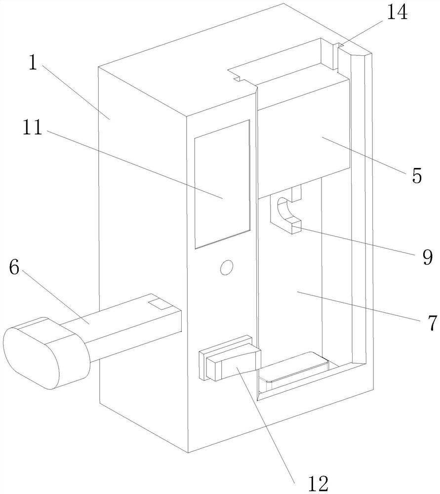
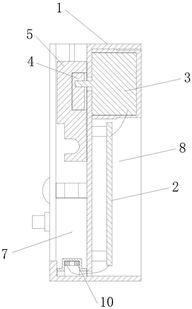
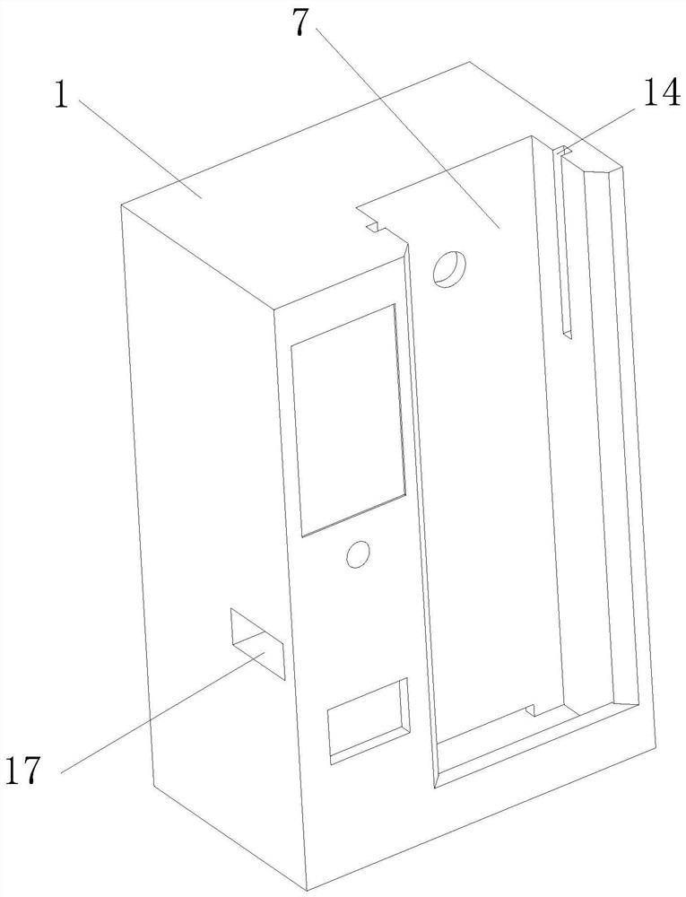
The invention discloses a lock detection device. A fixed frame is provided with a detection slot and a placement cavity, a moving block is vertically slid in the detection slot, a control circuit and a drive mechanism are located in the placement cavity, and the control circuit is electrically connected with the drive mechanism. The driving mechanism drives the moving block to move, the bottom of the moving block is provided with a push-pull hook, the bottom of the detection slot is provided with a wireless transmitter, and the clamping block is inserted into the detection slot. The detection method includes the following steps: issuing an unlocking instruction, the driving device drives the lock beam to move, and detects the current of the driving device to determine whether the unlocking is normal. times, and so on. The advantages of the invention are: through the control circuit, the driving mechanism is controlled to drive the moving block to perform unlocking and locking operations, so that manual control is not required, monitoring is performed automatically, manual switching is simulated, and switching times are automatically recorded.

Description

technical field [0001] The invention relates to a lock detection device and a detection method. Background technique [0002] With the intelligent development of the distribution network, more and more power distribution equipment, and more and more corresponding locking devices, such as electronic padlocks, and the existing electronic padlocks gradually become jammed or even unable to be opened after a period of application. As a result, the distribution network operation cannot be completed in time, which affects the safe operation of distribution network equipment and the work efficiency of distribution network operators. [0003] According to the quality requirements of locks, electronic padlocks need to be checked and inspected before leaving the factory, and the various indicators of the locks should be strictly tested, such as lock life test, salt spray test, high and low temperature test, etc. Among them, the salt spray test and high and low temperature test are carr...

Claims


Application Information

Patent Timeline
Patent Type & Authority Patents(China)
IPC IPC(8): G01R31/00
CPCG01R31/003
Inventor 顾建炜秦奋张鹏钱少锋刘宏伟洪建兵王群飞黄卫升
Owner STATE GRID ZHEJIANG ELECTRIC POWER CO LTD HANGZHOU POWER SUPPLY CO
Why Eureka
Try Eureka