Clock device based on LED lamp bead display

A technology of LED lamp bead and clock device, which is applied in the field of digital electronics, can solve the problems of increasing maintenance costs, performance, and cost not as good as digital clocks, and high cost

Inactive Publication Date: 2020-07-07
陕西天道必成信息技术有限责任公司
View PDF0 Cites 0 Cited by
  • Summary
  • Abstract
  • Description
  • Claims
  • Application Information

AI Technical Summary

Problems solved by technology

Traditional clocks are mechanical clocks. Although they can display time, they are not as good as digital clocks in terms of performance and cost due to limitations in mechanical structure, power, and volume.
[0003] Most of the currently used digital clocks use LED digital tubes as display modules, and select LED digital tubes of corresponding sizes according to the size of the display clock. Due to the high cost of digital tubes, the cost of digital clocks is high, and if LED digital Even if a section of any display bit is broken or damaged, the entire display bit needs to be removed and replaced. On the one hand, the maintenance cost is increased, and on the other hand, the welding process requirements for maintenance are also greatly improved.

Method used


Image

  • Clock device based on LED lamp bead display
  • Clock device based on LED lamp bead display
  • Clock device based on LED lamp bead display

Examples


Embodiment 1

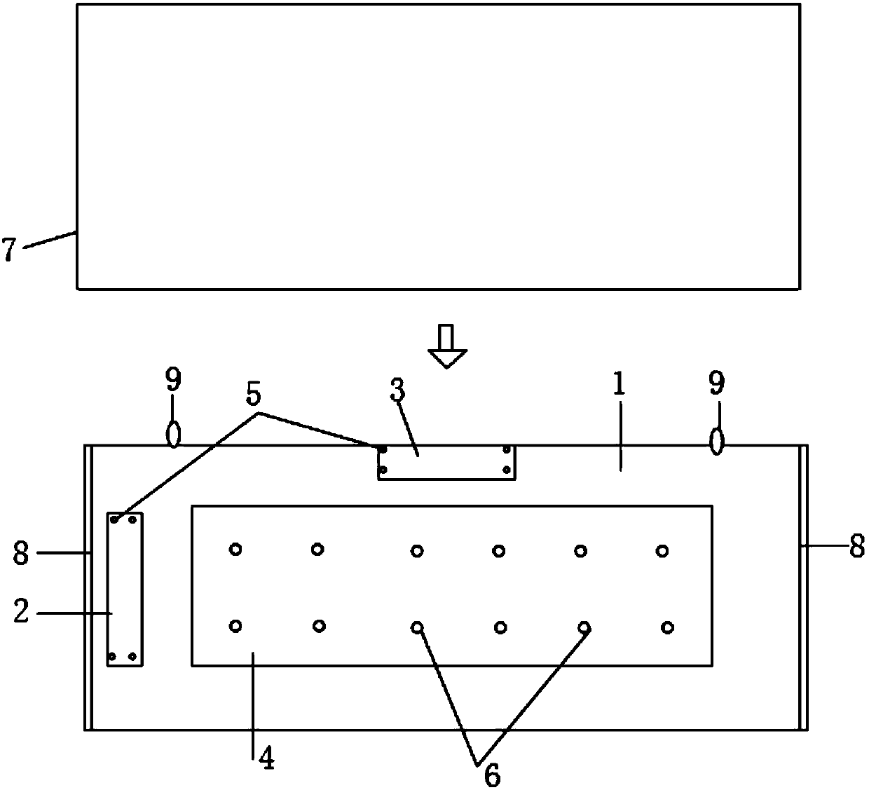
[0021] See figure 1 , figure 1 It is a structural schematic diagram of a clock device based on LED lamp bead display provided by the present invention.

[0022] The present invention provides a clock device based on LED bead display, which specifically includes:

[0023] Housing 1, main board 2, power board 3, LED bead display board 4, glass 7, card slot 8 and hook 9, wherein the main board 2 is connected to the power board 3 and the LED bead display board 4 respectively connection, the main board 2 is also connected to the casing 1, the power supply board 3 is connected to the casing 1, the LED lamp bead display board 4 is connected to the casing 1, and the glass 7 passes through the The card slot 8 is connected with the housing 1 , and the hook 9 is connected with the housing 1 .

[0024] In the embodiment of the present invention, a first stud 5 is also included, and the main board 2 and the power board 3 are respectively connected to the housing 1 through the first stud...

Embodiment 2

[0066] see again figure 1 , the present invention provides a clock device based on LED bead display, including: a housing 1, a main board 2, a power board 3, an LED bead display board 4, a glass 7, a card slot 8 and a hook 9, wherein the The main board 2 is respectively connected with the power board 3 and the LED display board 4, the main board 2 is also connected with the housing 1, the power board 3 is connected with the housing 1, and the LED light The bead display board 4 is connected to the housing 1 , the glass 7 is connected to the housing 1 through the slot 8 , and the hook 9 is connected to the housing 1 .

[0067] In the embodiment of the present invention, a first stud 5 is also included, and the main board 2 and the power board 3 are respectively connected to the housing 1 through the first stud 5 .

[0068] Preferably, the casing 1 is painted with iron casing, for example, black or gray.

[0069] Further, the first stud 5 is located at the bottom of the housing...


PUM


Abstract

The invention relates to a clock device based on LED lamp bead display. The clock device comprises a shell (1), a mainboard (2), a power panel (3), an LED lamp bead display panel (4), glass (7), a clamping groove (8) and a hook (9), wherein the mainboard (2) is respectively connected with the power panel (3) and the LED lamp bead display panel (4); the mainboard (2) is further connected with the shell (1), the power panel (3) is connected with the shell (1), the LED lamp bead display panel (4) is connected with the shell (1), the glass (7) is connected with the shell (1) through the clamping groove (8), and the hook (9) is connected with the shell (1). According to the embodiment of the invention, the cost of the digital clock is greatly reduced, the after-sales maintenance is more convenient and faster, and the maintenance cost is reduced.

Description

technical field [0001] The invention belongs to the technical field of digital electronics, and in particular relates to a clock device based on LED lamp bead display. Background technique [0002] From the middle of the 20th century to the beginning of the 21st century, electronic technology, especially digital electronic technology, has developed rapidly. Under its impetus, modern electronic products have penetrated into various fields of society. Digital electronic technology has effectively promoted the development of social productivity and the improvement of social informatization. At the same time, it has enhanced the performance of modern electronic products and accelerated the speed of product replacement. With the development of technology, the pace of people's life is accelerated, and time is money for us. Traditional clocks are mechanical clocks. Although they can display time, they are not as good as digital clocks in terms of performance and cost due to the li...

Claims


Application Information

Patent Timeline
Patent Type & Authority Applications(China)
IPC IPC(8): G04G9/10G04G17/02G04G17/04
CPCG04G9/10G04G17/02G04G17/04
Inventor 欧烨
Owner 陕西天道必成信息技术有限责任公司
Why Eureka
Try Eureka