Feed system, array antenna, and base station

A feeding system and array antenna technology, applied in stripline feeding arrays, linear waveguide feeding arrays, antenna arrays that are powered independently, etc. question

Inactive Publication Date: 2020-07-07
HUAWEI TECH CO LTD
View PDF5 Cites 7 Cited by
  • Summary
  • Abstract
  • Description
  • Claims
  • Application Information

AI Technical Summary

Problems solved by technology

[0004] but, figure 1 The antenna feeding network shown cannot support the miniaturization of the antenna, especially the multi-frequency antenna, which is bulky and inconvenient for pr

Method used


Image

  • Feed system, array antenna, and base station
  • Feed system, array antenna, and base station
  • Feed system, array antenna, and base station

Examples


Embodiment Construction

[0034] Before introducing the embodiment of this application, first explain the related terms involved in the embodiment of this application:

[0035] 1) Coupling connection (or coupling grounding)

[0036] There is a capacitance effect between two metals that are close to each other and have a coupling area. When the capacitance value is appropriate, the radio frequency signal can be transmitted between the two non-contact metals.

[0037] 2) Directly connected (or directly grounded)

[0038] Direct contact between metals enables radio frequency or direct current signals to be transmitted between metals.

[0039] 3) Polarized path

[0040] The feed system that feeds the radiating element needs to separate the feed according to the polarization of the radiating element, so all channels of the feeding system for one polarization of the radiating element are called polarization paths.

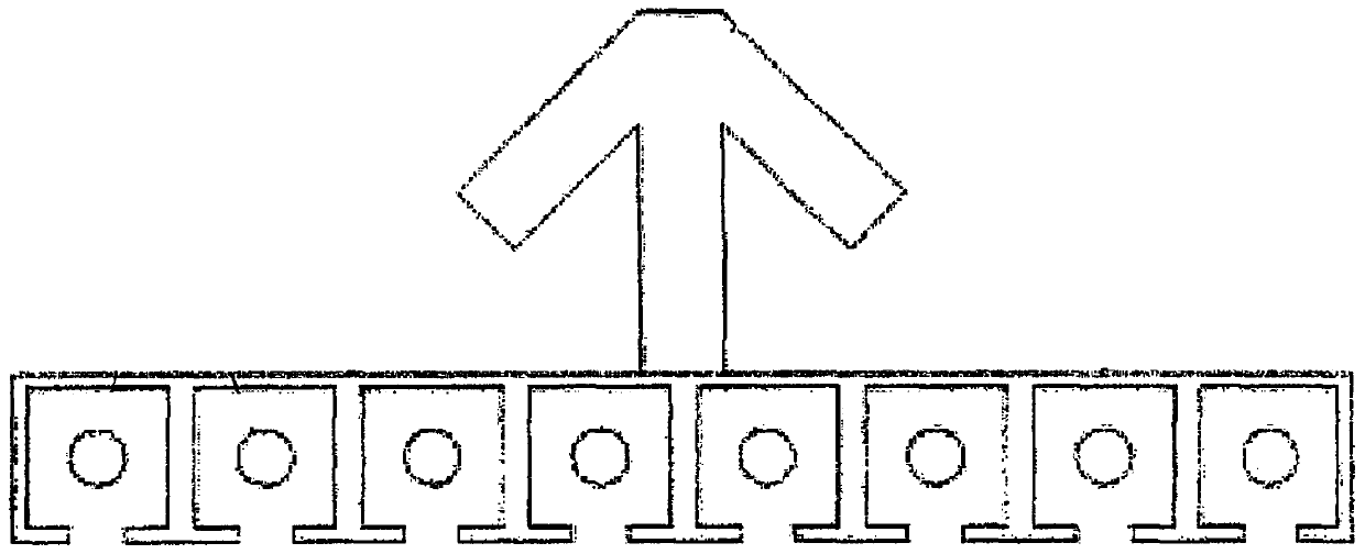
[0041] 4) Array antenna

[0042] An antenna system that consists of several identical vib...


PUM


Abstract

The embodiment of the invention provides a feed system, an array antenna, and a base station, and relates to the technical field of mobile communication. The phase-shifting feed system is simple in structure. The feed system is located on the back face of a metal plate and comprises a plurality of first feed cavities and a plurality of first feed strip lines suspended in the first feed cavities. Each first feed strip line in the plurality of first feed strip lines comprises a plurality of output ports, and the plurality of first feed cavities and the grounding layer of the metal plate share ametal surface; the metal surface is provided with a plurality of openings corresponding to the plurality of first radiation units on the front surface of the metal plate. The plurality of output portsof each first feed strip line are connected with the plurality of first radiation units one by one through the plurality of openings, and the plurality of first feed strip lines are used for providing transmission signals for the plurality of first radiation units.

Description

technical field [0001] The embodiments of the present application relate to the technical field of mobile communications, and in particular, to a feeding system, an array antenna, and a base station. Background technique [0002] With the development of multi-frequency and multi-system mobile communication systems, base station antennas also require multi-frequency and multi-polarization. However, when designing a multi-frequency antenna, because there are many frequency bands, the connection of the feed network is very complicated. The production man-hours of conventional components and cables are high, the assembly is difficult, and the loss of the entire system is high. [0003] Such as figure 1 As shown, the antenna feed network includes at least one feeder, and each feeder is a coaxial line, including inner and outer conductors; the outer conductor adopts a stretched profile tube, and the profile tube has a slit along the stretching direction (that is, it is in line wi...

Claims


Application Information

Patent Timeline
IPC IPC(8): H01Q21/00H01Q21/30H01Q1/50H01Q1/48H01Q1/24
CPCH01Q21/0081H01Q21/30H01Q1/50H01Q1/48H01Q1/246H01Q21/08H01Q5/42H01Q5/48H01Q21/24H01Q21/0037
Inventor 金莉李超超肖伟宏万振兴
Owner HUAWEI TECH CO LTD
Why Eureka
Try Eureka