Polishing device for electromechanical equipment machining
A technology of electromechanical equipment and polishing devices, which is applied in the direction of grinding drive devices, metal processing equipment, grinding/polishing equipment, etc., can solve the problems of unstable fixing, affecting the effect of processing and polishing, and deviation of workpieces, etc., and achieves good fixing effect, The effect of reducing the instability of the fixation and increasing the contact area
- Summary
- Abstract
- Description
- Claims
- Application Information
AI Technical Summary
Problems solved by technology
Method used
Image
Examples
Embodiment 1
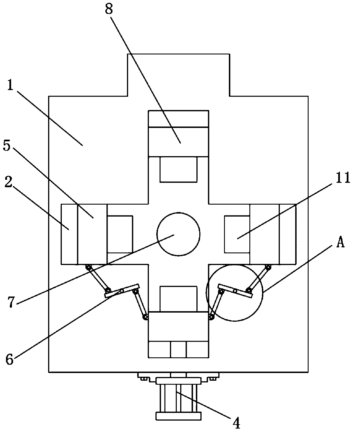
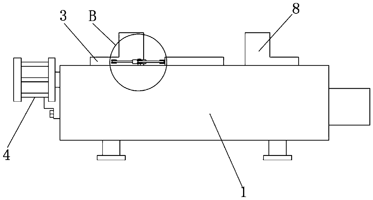
[0031] See Figure 1-4 , The present invention provides a technical solution: a polishing device for electromechanical equipment processing, comprising a worktable 1, the surface of the worktable 1 is provided with a "cross-shaped" movable groove 2 arranged in the movable groove 2 and the movable groove 2 For the matching active block 3, a cylinder 4 is provided on one side of the worktable 1, and the free end of the output shaft of the cylinder 4 is fixedly connected with the active block 3. The worktable 1 and the active block 3 are provided with two symmetrically distributed clamps in the vertical direction Block 5, the two clamping blocks 5 are both located in the movable groove 2, and the active block 3 and the clamping block 5 move synchronously through the linkage mechanism 6.
[0032] The center of the surface of the worktable 1 is provided with a groove 7 matching the workpiece, and the groove 7 is cylindrical.
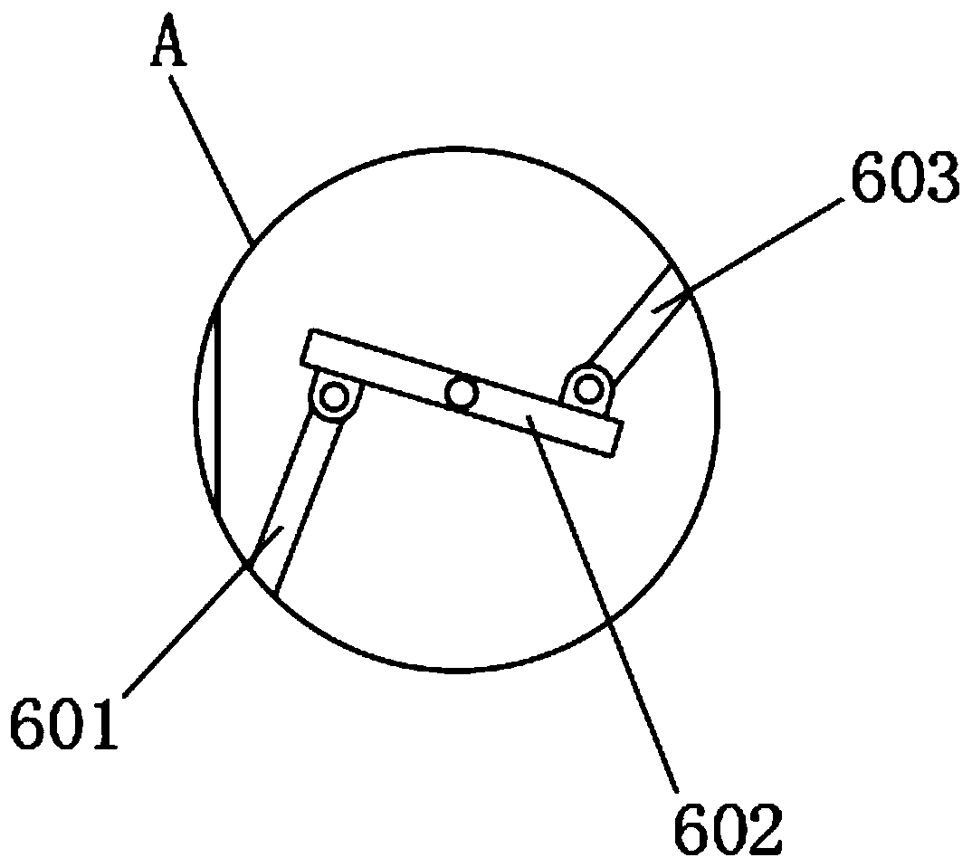
[0033] The linkage mechanism 6 includes a connecting rod 60...
Embodiment 2
[0036] See Figure 5 On the basis of the first embodiment, the present invention also provides a technical solution;
[0037] A clamping block 8 is arranged at a position symmetrical to the active block 3 on the worktable 1. The clamping block 8, the active block 3 and the two clamping blocks 5 are distributed in a "cross" shape, and the clamping block 8 is located in the movable slot 2. , The bottom of the clamping block 8 moves synchronously with the active block 3 through the pushing mechanism 9.
[0038] The pushing mechanism 9 includes a driving toothed plate 901, a gear 902, and a driven toothed plate 903. A movement slot 10 is opened in the worktable 1. The driving toothed plate 901, gear 902 and driven toothed plate 903 are all located in the movement slot 10. Inside, the driving toothed plate 901 is fixed to the bottom of the driving block 3, the gear 902 is rotatably connected with the worktable 1 through a rotating shaft, the gear 902 is arranged above the driving toothe...
Embodiment 3
[0041] See Image 6 On the basis of the first embodiment, the present invention also provides a technical solution;
[0042] The side of the splint 11 close to the center of the worktable 1 is curved. Specifically, increasing the contact area with the workpiece during clamping and fixing can make the overall fixing effect better, and it is not easy to produce subtle and splint 11 during the polishing process. Internal collision.
[0043] A specific application of the first, second and third embodiments of the present invention is:
[0044] When in use, place the toroidal workpiece in the groove 7 of the worktable 1, and run the cylinder 4, and the cylinder 4 drives the active block 3 to move along the movable groove 2. From the top view, the active block 3 moves upward When the active block 3 moves, the linkage mechanism 6 drives the clamping block 5 to move. When the active block 3 moves upward, the connecting rod 601 rotates and follows the active block 3, and the connecting rod 6...
PUM
 Abstract
Description
Claims
Application Information
 - R&D
- Intellectual Property
- Life Sciences
- Materials
- Tech Scout
- Unparalleled Data Quality
- Higher Quality Content
- 60% Fewer Hallucinations
Browse by: Latest US Patents, China's latest patents, Technical Efficacy Thesaurus, Application Domain, Technology Topic, Popular Technical Reports.
© 2025 PatSnap. All rights reserved.Legal|Privacy policy|Modern Slavery Act Transparency Statement|Sitemap|About US| Contact US: help@patsnap.com


