Two-way floating force-increasing clamping mechanism for high-pressure sealing

A clamping mechanism and high-pressure sealing technology, used in workpiece clamping devices, manufacturing tools, etc., can solve the problems of large space occupation, large air consumption, influence, etc., and achieve the effect of compact structure and small space occupation

Pending Publication Date: 2020-07-10
尊道(上海)自动化设备有限公司
View PDF0 Cites 2 Cited by
  • Summary
  • Abstract
  • Description
  • Claims
  • Application Information

AI Technical Summary

Problems solved by technology

[0002] In the prior art, when testing the airtightness of a product, such as a tubular automobile engine fuel distributor, the left and right ends of the workpiece to be tested need to be sealed and filled into the tube cavity Detection of gas, the detection of gas exerts a large reaction force on the end sealing structure of the workpiece to be detected, so the left and right ports need a large sealing force, and two extra large cylinders need to be configured, and the rigidity of the structure needs to be strong, and the consumption It has a large air volume and takes up a lot of space. It cannot be configured when the space is tight, and it will also affect and destroy the positioning of the workpiece.

Method used


Image

  • Two-way floating force-increasing clamping mechanism for high-pressure sealing
  • Two-way floating force-increasing clamping mechanism for high-pressure sealing
  • Two-way floating force-increasing clamping mechanism for high-pressure sealing

Examples


Embodiment Construction

[0019] The present invention will be described in detail below in conjunction with the accompanying drawings.

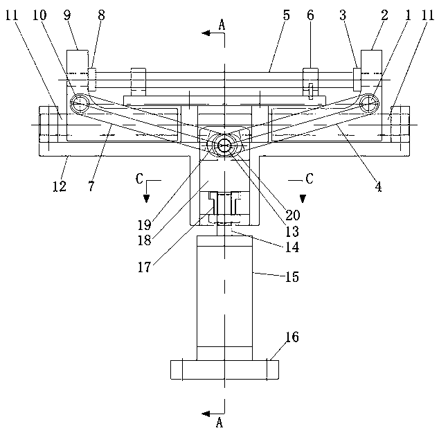
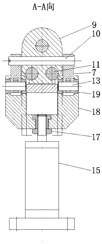
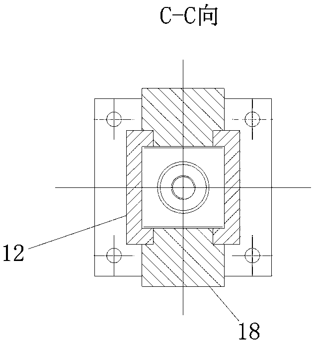
[0020] Such as Figure 1-5 As shown, a bidirectional floating booster clamping mechanism for high pressure sealing includes a base 12, a large cylinder 15 located below the base 12, a push-pull block 18 connected to the upper end of the piston rod 14 of the large cylinder 15, and a push-pull block 18 arranged on the base 12. The positioning tool 6 in the middle of the upper end and the left slider indenter 9 and the right slider indenter 2 that are slidably arranged on the base 12 facing each other, the left slider indenter 9 and the right slider indenter 2 are located on the positioning tool 6 The left and right sealing pads 8 and 3 are respectively arranged on the left and right sides of the workpiece position, and the push-pull block 18 is arranged in the chute at the bottom of the base 12, and the middle part of the push-pull block 18 is hinged with the left conn...


PUM


Abstract

The invention provides a two-way floating force-increasing clamping mechanism for high-pressure sealing. The mechanism comprises a base, a large air cylinder located below the base, a push-pull blockconnected with the upper end of a piston rod of the large air cylinder, a positioning tooling arranged in the middle of the upper end of the base as well as a left slider press head and a right sliderpress head which are directly opposite to each other and arranged on the base in a sliding manner, a left sealing gasket and a right sealing gasket are arranged on the left side and the right side, located in the workpiece positions of the positioning tooling, of the left slider press head and the right slider press head respectively, the push-pull block is arranged in a sliding groove formed inthe lower part of the base, a left connecting rod and a right connecting rod are hinged to the middle of the push-pull block through central drive pins, the left connecting rod is hinged with the leftslider press head through a left drive pin, and the right connecting rod is hinged with the right slider press head through a right drive pin. The mechanism is compact in structure and occupies smallspace; by adoption of the force-increasing principle, a relatively large blocking force requirement of ports of a to-be-detected workpiece can be met by one air cylinder; and clamping force of the ports on two sides of the to-be-detected workpiece can be balanced adaptively, and the positioning of the workpiece cannot be affected by the clamping force.

Description

technical field [0001] The invention relates to the technical field of airtightness testing equipment, in particular to a bidirectional floating booster clamping mechanism for high-pressure sealing. Background technique [0002] In the prior art, when testing the airtightness of a product, such as a tubular automobile engine fuel distributor, the left and right ends of the workpiece to be tested need to be sealed and filled into the lumen after sealing. Detection of gas, the detection of gas exerts a large reaction force on the end sealing structure of the workpiece to be detected, so the left and right ports need a large sealing force, and two extra-large cylinders need to be configured, and the rigidity of the structure needs to be strong. It has a large air volume and takes up a lot of space. It cannot be configured when the space is tight, and it will also affect and destroy the positioning of the workpiece. [0003] Therefore, there is an urgent need in the prior art f...

Claims


Application Information

Patent Timeline
Patent Type & Authority Applications(China)
IPC IPC(8): B25B11/00
CPCB25B11/00
Inventor 贺红欣
Owner 尊道(上海)自动化设备有限公司
Why Eureka
Try Eureka