Drum handling device

A technology for handling devices and oil drums, which is used in transportation and packaging, trolley accessories, multi-axis trolleys, etc., and can solve problems such as reducing work efficiency, rolling oil drums, and not being able to grasp the driving direction well.

Inactive Publication Date: 2021-05-18
唐山曹妃甸实华原油码头有限公司
View PDF17 Cites 0 Cited by
  • Summary
  • Abstract
  • Description
  • Claims
  • Application Information

AI Technical Summary

Problems solved by technology

[0003] The above-mentioned existing technical solutions have the following defects: pushing the oil drum carrier in parallel is more laborious and time-consuming; there is no protective device for the oil drum on the oil drum carrier, and the oil drum may move forward, backward, left, and right on the bottom plate during transportation , the center of gravity is unstable, the driving direction cannot be well grasped, and the oil drum will roll off the car, resulting in damage to the oil drum and reducing work efficiency

Method used


Image

  • Drum handling device
  • Drum handling device
  • Drum handling device

Examples


Embodiment 1

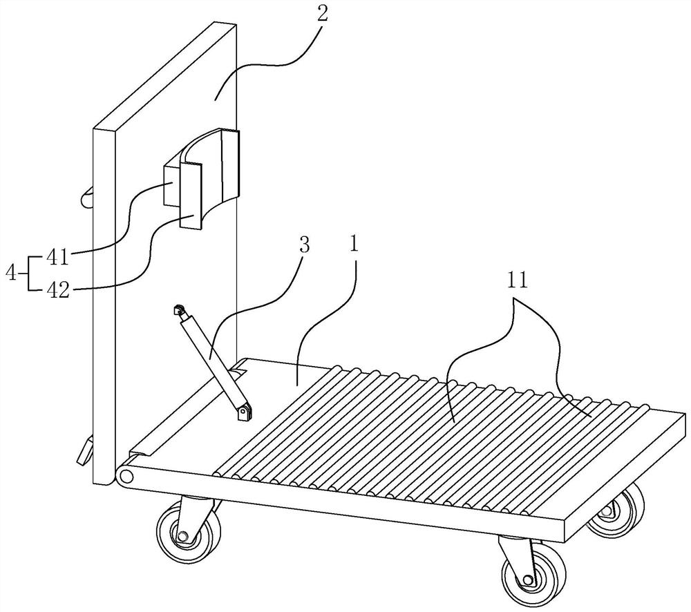
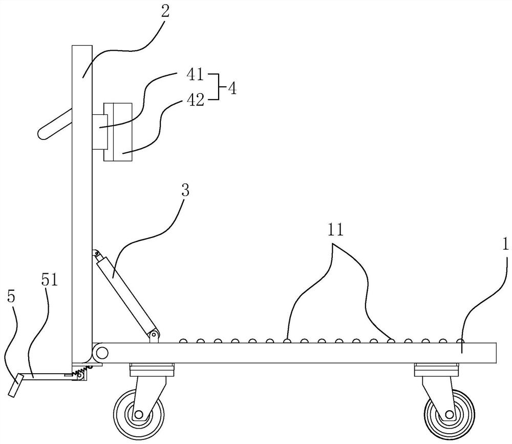
[0052] refer to Figure 6 and Figure 7 , there is a groove 21 on the support plate 2, the groove 21 is located above the connection between the control assembly 3 and the support plate 2, refer to Figure 8 Each of the two inner sides of the groove 21 is provided with an inward L-shaped chute 211, and the left and right sides of the connecting seat 41 are respectively provided with an L-shaped slider 411 used in conjunction with the chute 211, The top of the connection seat 41 is provided with a vertical plate 412 positioned in the groove 21, and the support plate 2 is provided with a plurality of threaded holes arranged side by side up and down. The fixed connection of the two threaded holes determines the up and down movement position of the vertical plate 412.

[0053] The implementation principle of this embodiment is: before the oil drum is transported to the device, according to the height of the oil drum and the amount of liquid in it, the support frame 4 is first di...

Embodiment 2

[0055] refer to Figure 9 and Figure 10 , the support plate 2 has a groove 21, the groove 21 is located above the connection between the control assembly 3 and the support plate 2, and an inward L-shaped chute 211 is formed on the two inner sides of the groove 21, connecting The left and right sides of the seat 41 are each provided with an L-shaped slide block 411, which is used in conjunction with the chute 211. The threaded hole provided on the top of the support plate 2 communicates with the groove 21, and a threaded rod 22 is inserted in the threaded hole. The end of the threaded rod 22 is provided with a circular turning block 23, and the top of the connecting seat 41 has a circular groove 413 inwardly. The movement in and out of the threaded hole makes the rotary block 23 rotate in the circle 413 and controls the connecting seat 41 to move up and down in the groove 21 .

[0056] The implementation principle of this embodiment is: before the oil barrel is transported t...


PUM


Abstract

The invention relates to the technical field of wharf transportation machinery, in particular to an oil drum handling device, which includes a bottom plate for placing the oil drum and a support plate for supporting the oil drum. The device also includes a control assembly for controlling the inclination of the support plate, a support frame for limiting the position of the oil drum, and a foot support for maintaining the balance of the device during the inclination of the support plate. The movable end of the control assembly is connected with the support plate, and its fixed end is connected with the bottom plate. connected, the support frame is arranged at the bottom of the support plate. The control assembly of the present invention can freely control the inclination angle of the support plate and lower the center of gravity of the oil drum so as to save labor and time when moving the oil drum handling device. The setting of the support frame and the boss on the bottom plate can protect and limit the oil drum, prevent the oil drum from moving freely during the handling process, stabilize the center of gravity of the oil drum, prevent the oil drum from rolling down, and avoid damage to the oil drum , also improves work efficiency.

Description

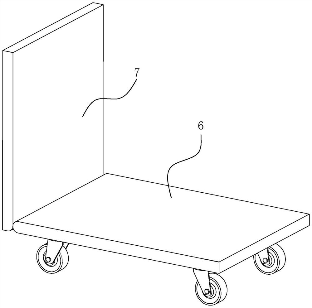
technical field [0001] The invention relates to the technical field of wharf transportation machinery, in particular to a labor-saving oil drum handling device capable of improving the stability of the oil drum. Background technique [0002] At present, in the process of oil transportation and storage at the terminal, it is inevitable to use oil drum trucks. figure 1 It is a structural schematic diagram of an existing oil drum truck, such as figure 1 As shown, the existing oil drum truck only has a base 6 and a vertical plate 7, and the bottom of the base 6 is provided with three or four wheels. [0003] The above-mentioned existing technical solutions have the following defects: pushing the oil drum carrier in parallel is more laborious and time-consuming; there is no protective device for the oil drum on the oil drum carrier, and the oil drum may move forward, backward, left, and right on the bottom plate during transportation , the center of gravity is unstable, the dri...

Claims


Application Information

Patent Timeline
Patent Type & Authority Patents(China)
IPC IPC(8): B62B3/02B62B3/10B62B5/00
CPCB62B3/007
Inventor 崔松
Owner 唐山曹妃甸实华原油码头有限公司
Why Eureka
Try Eureka