Lifting device for entrance and exit of parking lot

A technology for entrances and exits and parking lots, which is applied in the direction of roads, road signs, traffic signals, etc., and can solve problems such as instability of the lifting plate, displacement of the lifting plate, and vibration

Pending Publication Date: 2020-07-10
廊坊秉桓科技有限公司
View PDF8 Cites 4 Cited by
  • Summary
  • Abstract
  • Description
  • Claims
  • Application Information

AI Technical Summary

Problems solved by technology

[0003] In the current take-off and landing device at the entrance and exit of the parking lot, the lifting plate is usually directly driven by the motor, which easily causes the displacement of the lifting plate, making it difficult to maintain a stable level when the lifting plate i

Method used


Image

  • Lifting device for entrance and exit of parking lot
  • Lifting device for entrance and exit of parking lot
  • Lifting device for entrance and exit of parking lot

Examples


Embodiment 1

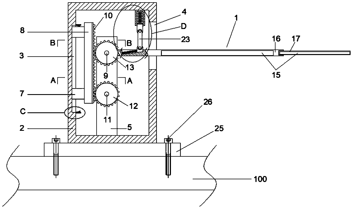
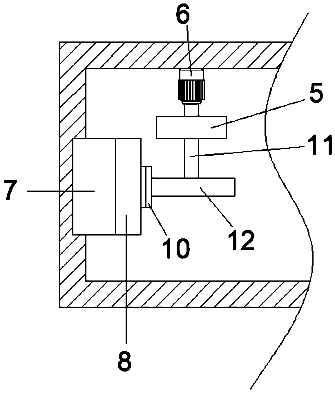
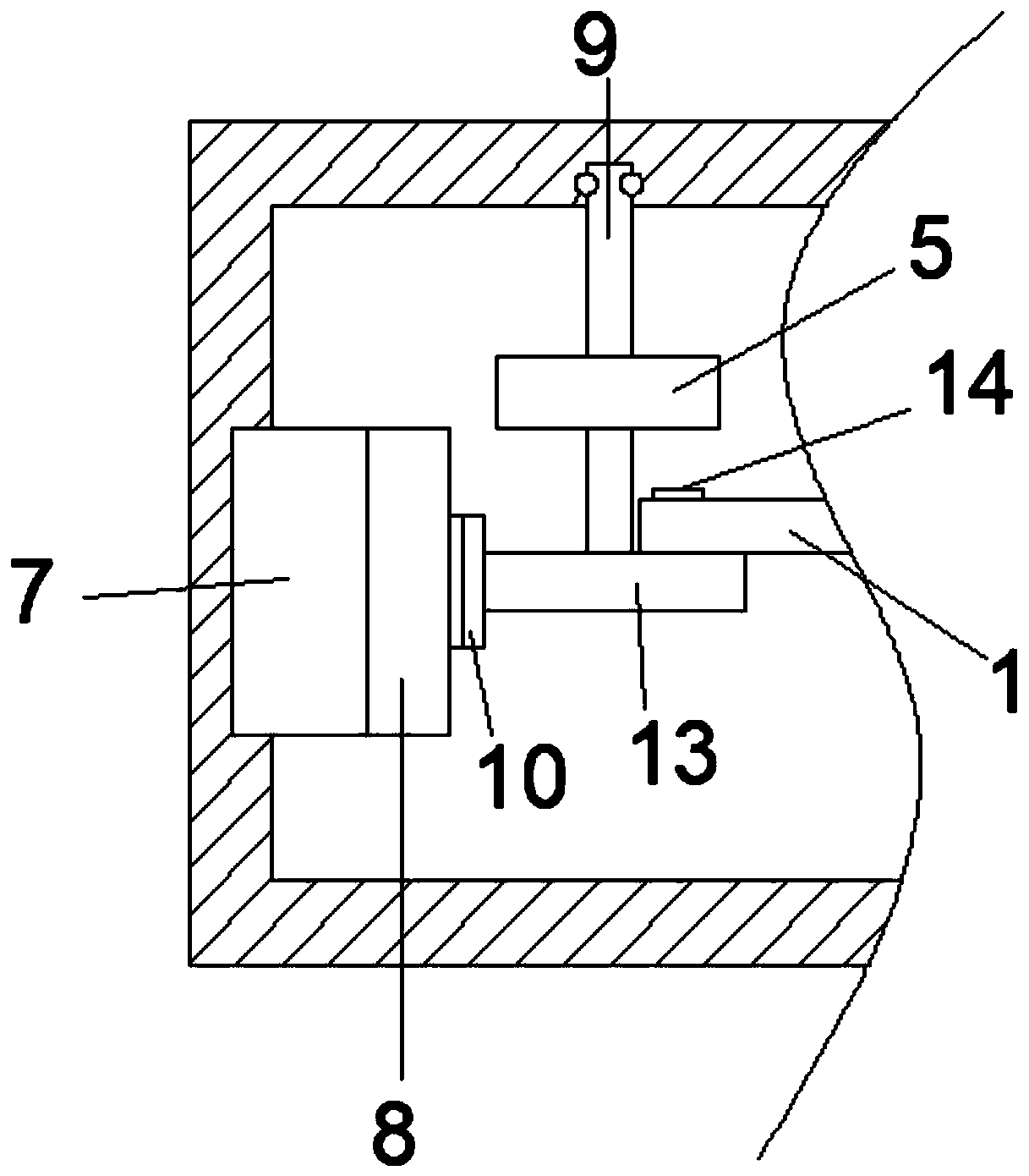
[0023] see Figure 1-5 , a lifting device for the entrance and exit of a parking lot, including a lifting rod 1, a drive assembly and an installation frame 2 for fixing and installing the drive assembly, the lifting rod 1 is arranged on the drive assembly, and the side inner wall of the installation frame 2 There is a first chute 3, and a through groove 4 is provided on the side of the installation frame 2 opposite to the first chute 3, and a support seat 5 is fixedly installed on the bottom inner wall of the installation frame 2, and the first slide Slider 7 is slidably installed in groove 3, and described slider 7 is arranged symmetrically, and described driving assembly comprises the drive motor 6 that is fixedly installed on the inner wall of installation frame 2 sides, the positioning plate 8 that is fixedly installed on slider 7 and the rotation installation The driven rotating shaft 9 on the inner wall of the side of the installation frame 2, the driven rotating shaft 9...

Embodiment 2

[0029] This embodiment is further improved on the basis of the embodiment. The improvement is that: both sides of the first chute 3 are provided with a limit assembly, and the limit assembly includes a travel switch 27 and a travel switch 27 for fixed installation. The fixed seat 28 is fixedly installed on the side inner wall of the installation frame 2, and the travel switch 27 is electrically connected to the drive motor 6; by setting the travel switch 27, the travel switch 27 is electrically connected to the drive motor 6, effectively Control the limit position of the lifting rod 1 during the lifting process to avoid accidental collisions and damage to mechanical components.

[0030] The working principle of this embodiment is: by setting the travel switch 27, the travel switch 27 is electrically connected to the drive motor 6, effectively controlling the limit position of the lifting rod 1 during the lifting process, and avoiding accidental collisions that cause damage to m...


PUM


Abstract

The invention discloses a lifting device for entrance and exit of a parking lot. The device comprises a lifting rod, a driving assembly and a mounting frame. A supporting seat is fixedly mounted on the inner wall of the bottom of the mounting frame. The driving assembly comprises a driving motor, a positioning plate and a driven rotating shaft; a rack is fixedly installed on the positioning plate,a driving rotating shaft is fixedly installed at the output end of the driving motor, a driving gear is fixedly installed at the end of the driving rotating shaft, a driven gear is fixedly installedat the end of the driven rotating shaft, a positioning shaft is fixedly installed on the driven gear, and the lifting rod is fixedly installed on the positioning shaft. The driving motor is arranged;when the driving motor rotates, the driving rotating shaft and the driving tear are driven to rotate and the driven gear is driven to make rotation, so that the lifting rod is driven to swing and lift; the rack is used in cooperation with the driving gear and the driven gear in a meshed mode, swing lifting of the lifting rod is achieved, and a phenomenon that the lifting rod is prone to displacement because a driving motor directly drives the lifting rod to ascend or descend is avoided.

Description

technical field [0001] The invention relates to the field of public facilities, in particular to a take-off and landing device for parking lot entrances and exits. Background technique [0002] At present, with the protection of social security and the improvement of security requirements in various places, all kinds of existing parking lots have implemented entrance and exit management. Managed in and out at will. [0003] In the current take-off and landing device at the entrance and exit of the parking lot, the lifting plate is usually directly driven by the motor, which easily causes the displacement of the lifting plate, making it difficult to maintain a stable level when the lifting plate is working. In addition, the lifting plate is in the process of lifting. It is easy to vibrate due to inertia and gravity, causing the lifting plate to be unstable. Based on this, we propose a lift-off and landing device for parking lot entrances and exits to solve the above problems...

Claims


Application Information

Patent Timeline
IPC IPC(8): E01F13/06E01F9/619E01F9/669
CPCE01F13/06E01F9/619E01F9/669
Inventor 李春花
Owner 廊坊秉桓科技有限公司
Why Eureka
Try Eureka