A jacket base plate structure and a jacket comprising the bottom base plate structure
A jacket and template technology, applied in infrastructure engineering, underwater structures, buildings, etc., can solve the problems that cannot meet the needs of large-scale drilling and production platforms or central processing platform jacket transportation and launching, and achieve simple construction, Effects of reduced capacity requirements and reduced installation weight
- Summary
- Abstract
- Description
- Claims
- Application Information
AI Technical Summary
Problems solved by technology
Method used
Image
Examples
Embodiment 1
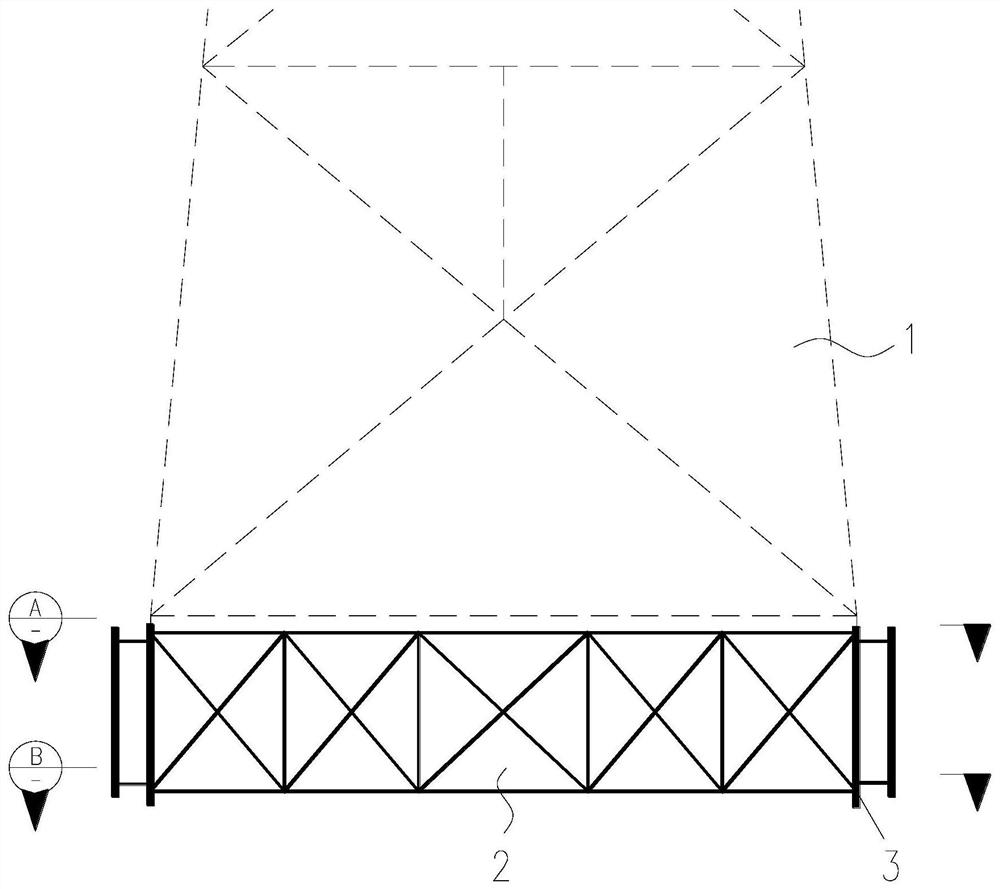
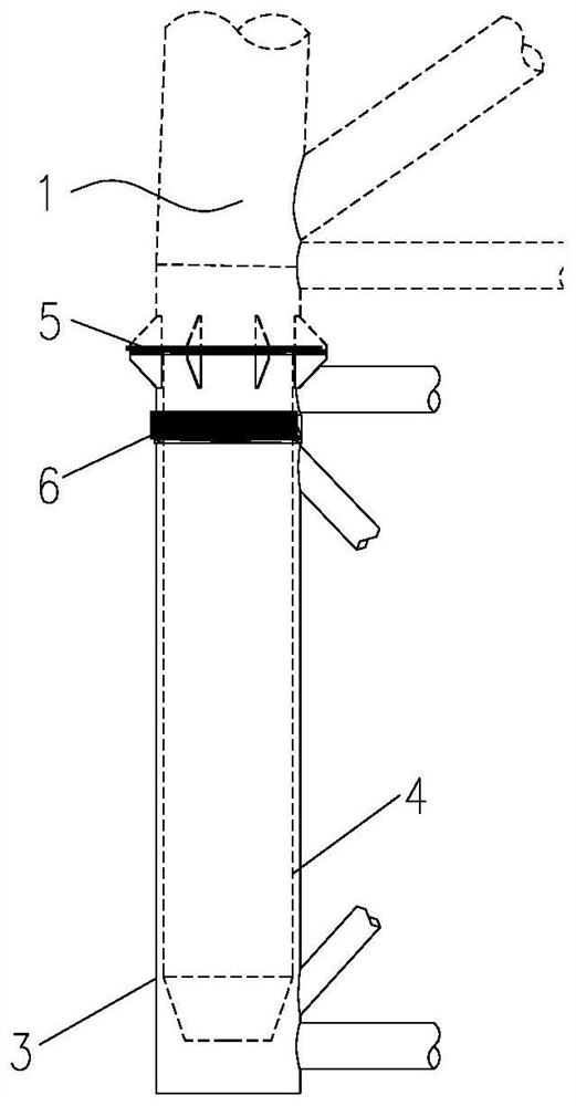
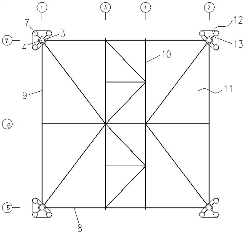
[0039] Such as figure 1 , figure 2 , image 3 As shown, this embodiment provides a base plate structure at the bottom of a large jacket in ultra-deep water, including the following components:
[0040] Base plate main legs 3, several of the base plate main legs 3 are vertically arranged below the jacket main body structure 1 and distributed in a polygonal shape; the top of each of the base plate main legs 3 is provided with a support pad 5, and each of the base plate main legs 3 A pile holder 6 is provided near the top of the main leg 3 of the base plate;
[0041] Pile group sleeves 7, several groups of pile group sleeves 7 are respectively connected to the corresponding main legs 3 of the base plate through connecting plates, and the inside of each group of pile group sleeves 7 is provided with a fixing device driven into the seabed. pile;
[0042]The horizontal façade frame 8 and the first vertical façade frame 9 , the base plate main legs 3 are sequentially and alterna...
Embodiment 2
[0044] Such as figure 1 , figure 2 , image 3 , Figure 7 As shown, this embodiment provides a base plate structure at the bottom of a large jacket in ultra-deep water, including the following components:
[0045] Base plate main legs 3, several of the base plate main legs 3 are vertically arranged below the jacket main body structure 1 and distributed in a polygonal shape; the top of each of the base plate main legs 3 is provided with a support pad 5, and each of the base plate main legs 3 A pile holder 6 is provided near the top of the main leg 3 of the base plate;
[0046] Pile group sleeves 7, several groups of pile group sleeves 7 are respectively connected to the corresponding main legs 3 of the base plate through connecting plates, and the inside of each group of pile group sleeves 7 is provided with a fixing device driven into the seabed. pile;
[0047] The horizontal façade frame 8 and the first vertical façade frame 9 , the base plate main legs 3 are sequential...
Embodiment 3
[0052] Such as Figures 1 to 8 As shown, this embodiment provides a base plate structure at the bottom of a large jacket in ultra-deep water, including the following components:
[0053] Base plate main legs 3, several of the base plate main legs 3 are vertically arranged below the jacket main body structure 1 and distributed in a polygonal shape; the top of each of the base plate main legs 3 is provided with a support pad 5, and each of the base plate main legs 3 A pile holder 6 is provided near the top of the main leg 3 of the base plate;
[0054] Pile group sleeves 7, several groups of pile group sleeves 7 are respectively connected to the corresponding main legs 3 of the base plate through connecting plates, and the inside of each group of pile group sleeves 7 is provided with a fixing device driven into the seabed. pile;
[0055] The horizontal façade frame 8 and the first vertical façade frame 9 , the base plate main legs 3 are sequentially and alternately connected th...
PUM
 Abstract
Description
Claims
Application Information
 - R&D
- Intellectual Property
- Life Sciences
- Materials
- Tech Scout
- Unparalleled Data Quality
- Higher Quality Content
- 60% Fewer Hallucinations
Browse by: Latest US Patents, China's latest patents, Technical Efficacy Thesaurus, Application Domain, Technology Topic, Popular Technical Reports.
© 2025 PatSnap. All rights reserved.Legal|Privacy policy|Modern Slavery Act Transparency Statement|Sitemap|About US| Contact US: help@patsnap.com


