
Electric control box mounting assembly and air conditioner

A technology for installing components and electric control boxes, applied in the field of air conditioners, can solve problems such as affecting air volume and air duct obstruction, and achieve the effect of avoiding obstruction, smooth air duct flow, and good installation space

Pending Publication Date: 2020-07-10
NINGBO AUX ELECTRIC +1
View PDF0 Cites 0 Cited by
  • Summary
  • Abstract
  • Description
  • Claims
  • Application Information

AI Technical Summary

Problems solved by technology

[0002] At present, the existing air-conditioning indoor units, such as wind cabinet products, usually place the electric control box in the middle of the whole machine, which hinders the air duct and affects the air volume

Method used


Image

  • Electric control box mounting assembly and air conditioner
  • Electric control box mounting assembly and air conditioner
  • Electric control box mounting assembly and air conditioner

Examples


no. 1 example

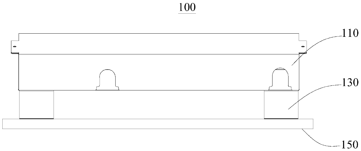
[0045] see in conjunction Figure 1 to Figure 3 , this embodiment provides an electric control box installation assembly 100, which avoids obstruction to the air duct, improves the air volume of the air duct, and at the same time, is quick and convenient to install, simple to operate, labor-saving, high in assembly efficiency, and convenient to route. Neat, less error-prone, and mutual influence between different lines can be avoided.

[0046] The electric control box installation assembly 100 provided in this embodiment includes an electric control box body 110, a mounting bracket 130 and a chassis 150, the chassis 150 is used to be arranged on the bottom of the air conditioner housing 210, the mounting bracket 130 is arranged on the chassis 150, and the electric control box The box body 110 is disposed on the mounting bracket 130 and located below the air duct in the air conditioner housing 210 .

[0047] It should be noted that the air conditioner casing 210 mentioned in t...

no. 2 example

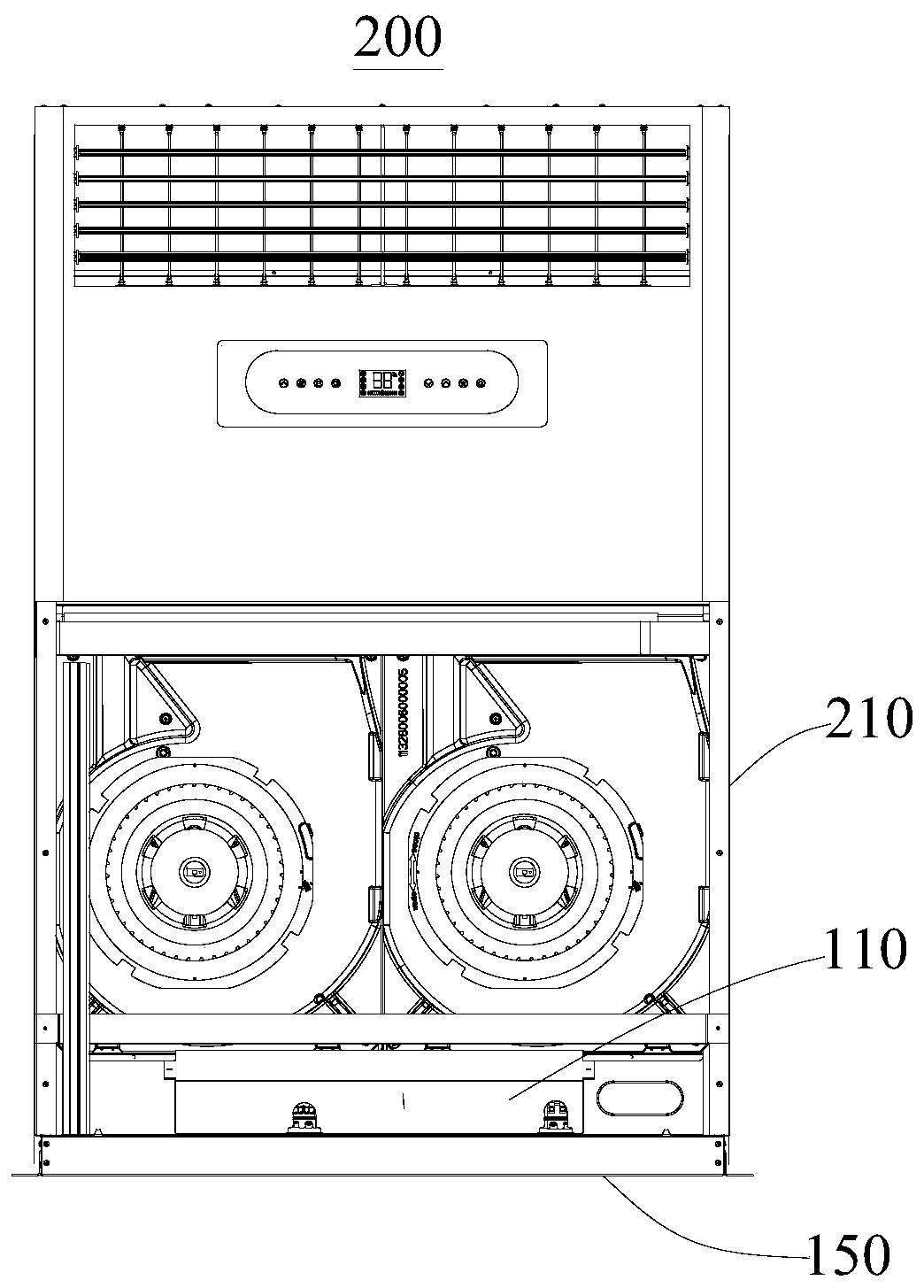
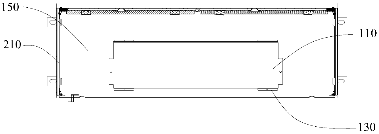
[0073] Please continue to see figure 2 and image 3 , this embodiment provides an air conditioner 200, including an air conditioner casing 210 and an electric control box installation assembly 100, wherein the basic structure, principle and technical effect of the electric control box installation assembly 100 are the same as those of the first embodiment, which is For a brief description, for parts not mentioned in this embodiment, reference may be made to the corresponding content in the first embodiment.

[0074] The electric control box installation assembly 100 includes the electric control box body 110, the mounting bracket 130 and the chassis 150, the chassis 150 is arranged on the bottom of the air conditioner housing 210, the installation bracket 130 is arranged on the chassis 150, and the electric control box body 110 is arranged on the installation bracket 130 above and below the air duct in the air conditioner casing 210 . By moving the electric control box body...


PUM


Abstract

The invention provides an electric control box mounting assembly and an air conditioner, and relates to the technical field of air conditioners. The electric control box mounting assembly comprises anelectric control box body, a mounting bracket and a bottom disk, wherein the bottom disk is arranged at the bottom of an air conditioner housing; the mounting bracket is arranged on the bottom disk;the electric control box body is arranged on the mounting bracket and is located below a wind channel in the air conditioner housing. According to the electric control box mounting assembly disclosedby the invention, the electric control box body is fixedly mounted on the bottom disk through the mounting bracket, so that the electric control box body is transferred to the bottom of the complete machine from the middle part of the complete machine; after being mounted to the right place, the electric control box body is located below the wind channel, so that the effect that the wind channel is impeded by the electric control box body is avoided, the streamline of the wind channel is smoother, and the wind amount is increased; and compared with the prior art, the electric control box mounting assembly provided by the invention prevents the impediment of the wind channel, and increases the wind amount of the wind channel.

Description

technical field [0001] The invention relates to the technical field of air conditioners, in particular to an electric control box installation assembly and an air conditioner. Background technique [0002] At present, the existing air-conditioning indoor units, such as wind cabinet products, usually place the electric control box in the middle of the whole machine, which hinders the air duct and affects the air volume. Contents of the invention [0003] The problem to be solved by the invention is how to make the streamline of the air duct smoother and increase the air volume. [0004] In order to solve the above problems, the present invention adopts the following technical solutions. [0005] In one aspect, the present invention provides an electric control box installation assembly, including an electric control box body, a mounting bracket and a chassis, the chassis is used to be arranged on the bottom of the air conditioner housing, and the installation bracket is ar...

Claims


Application Information

Patent Timeline
Patent Type & Authority Applications(China)
IPC IPC(8): F24F11/89F24F1/005
CPCF24F11/89F24F1/005
Inventor 沙凡柯得军董国龙
Owner NINGBO AUX ELECTRIC
Features
  • Generate Ideas
  • Intellectual Property
  • Life Sciences
  • Materials
  • Tech Scout
  • Unparalleled Data Quality
  • Higher Quality Content
  • 60% Fewer Hallucinations
Learn More