Multi-frequency antenna structure

A technology of multi-frequency antenna and antenna unit, applied in the direction of antenna, antenna array, antenna components, etc., can solve the problems of gain drop, polarization suppression ratio deterioration, etc.

Active Publication Date: 2020-07-10
HUAWEI TECH CO LTD
View PDF11 Cites 4 Cited by
  • Summary
  • Abstract
  • Description
  • Claims
  • Application Information

AI Technical Summary

Problems solved by technology

[0004] This application provides a multi-frequency antenna structure, which can solve the problems of polarization suppression ratio deterioration and gain drop at certain frequency points of the antenna unit's pattern in a certain frequency band.

Method used


Image

  • Multi-frequency antenna structure
  • Multi-frequency antenna structure
  • Multi-frequency antenna structure

Examples


Embodiment Construction

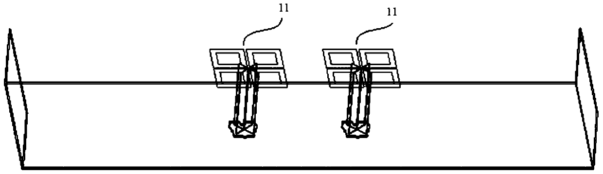
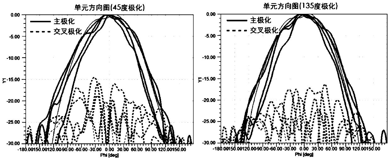
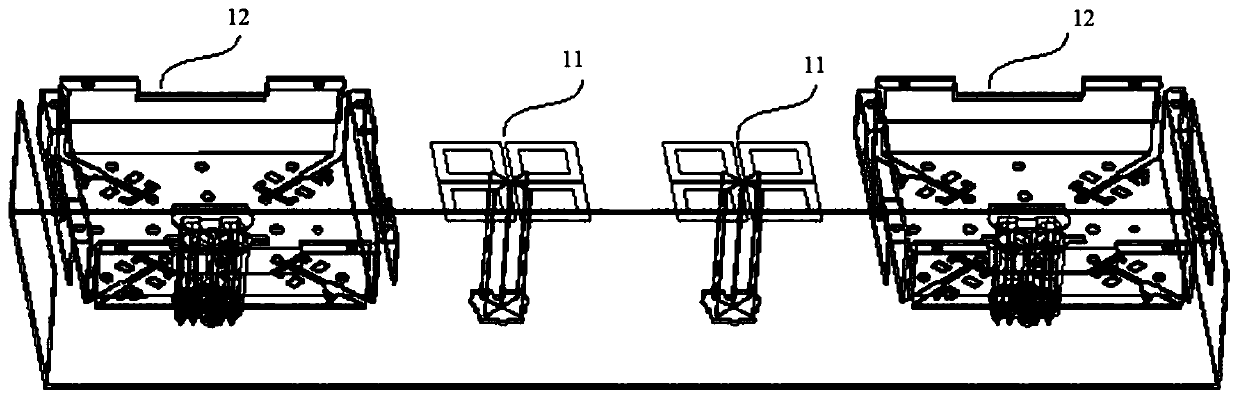
[0045] Such as Figure 1C with 1D As shown, after adding the antenna unit with the working frequency band of 0.7GHz to 0.9GHz, the radiation pattern of the antenna unit with the working frequency band of 1.7GHz to 2.7GHz appears to deteriorate the polarization suppression ratio at some frequency points (cross-polarization shown by the dotted line Radiation uplift), gain drop and other issues. In order to solve this technical problem, the present application provides a multi-frequency antenna structure.

[0046] This application considers increasing the parasitic structure of the antenna unit to solve the problems such as the deterioration of the planned suppression ratio and the drop of the gain in the pattern of the antenna unit. However, it is considered that if the parasitic structure is only added to the existing antenna structure, the following situation may occur: while optimizing the pattern of an antenna element in a certain frequency band, it will have a deteriorati...


PUM


Abstract

The invention provides a multi-frequency antenna structure. The multi-frequency antenna structure comprises a first antenna unit, a second antenna unit, a reflecting plate and a first parasitic structure of the first antenna unit, wherein the working frequency bands of the first antenna unit and the second antenna unit are different, and the distance between the antenna unit with the higher working frequency band and the reflecting plate is lessthan the distance between the antenna unit with the lower working frequency band and the reflecting plate; the first antenna unit is adjacent to the second antenna unit; the distance between the first antenna unit and the second antenna unit is less than 0.5 time of the vacuum wavelength of the minimum working frequency band in the two antenna units; the distance between the first antenna unit and the first parasitic structure is less than 0.5 times of the vacuum wavelength of the working frequency band of the first antenna unit, and the distance between the second antenna unit and the first parasitic structure is less than 0.5 times of the vacuum wavelength of the working frequency band of the second antenna unit. Therefore, the problems ofpolarization rejection ratio deterioration and the like of the directional diagram of the first antenna unit can be optimized, and the performance of the second antenna unit cannot be obviously influenced.

Description

technical field [0001] The present application relates to the technical field of antennas, in particular to a multi-frequency antenna structure. Background technique [0002] The common-aperture technology of the antenna refers to arranging the array antennas of multiple frequency bands on the same plane. Based on this, the overall size of the multi-frequency array antenna can be greatly reduced, and the application advantages of miniaturization, light weight, and easy deployment can be obtained. [0003] In the common-aperture technology, since the antenna units of different frequency bands are placed close to each other, the mutual coupling between the antenna units is serious, and the pattern index of the antenna unit deteriorates, which does not meet the predetermined specification requirements for the antenna unit. Figure 1A A schematic diagram of an antenna unit with a working frequency range of 1.7GHz to 2.7GHz provided for the prior art, wherein Figure 1A Taking two...

Claims


Application Information

Patent Timeline
Patent Type & Authority Applications(China)
IPC IPC(8): H01Q1/36H01Q5/00H01Q19/10H01Q21/00
CPCH01Q5/00H01Q1/36H01Q21/00H01Q19/10H01Q21/26H01Q1/521H01Q15/0013H01Q5/49H01Q5/48H01Q5/30H01Q15/00H01Q21/30
Inventor 罗兵肖伟宏覃雯斐
Owner HUAWEI TECH CO LTD
Why Eureka
Try Eureka