Anti-rebound device suitable for bomb fixing mechanism of cluster bomb separating device

A separation device and anti-rebound technology, applied in the direction of launching devices, safety devices, weapon accessories, etc., can solve the problems of unreasonable design, complex design structure, high cost, etc., and achieve the effect of simple structure, strong practicability and wide application range

Active Publication Date: 2020-07-14
SHANGHAI INST OF ELECTROMECHANICAL ENG
View PDF6 Cites 3 Cited by
  • Summary
  • Abstract
  • Description
  • Claims
  • Application Information

AI Technical Summary

Problems solved by technology

It includes an infrared sensor for sensing objects passing through the passage, a movable baffle that can block the passage after the object passes through, and a control unit for controlling the movement of the movable baffle. On one side of the channel, a limit column that can prevent the rotation of the movable baffle is provided on the other side of the channel. The probe of the infrared sensor is set in the channel between the column and the limit column, but the design structure is complicated and the cost is high. unreasonable design

Method used


Image

  • Anti-rebound device suitable for bomb fixing mechanism of cluster bomb separating device
  • Anti-rebound device suitable for bomb fixing mechanism of cluster bomb separating device
  • Anti-rebound device suitable for bomb fixing mechanism of cluster bomb separating device

Examples


Embodiment Construction

[0034] The present invention will be described in detail below in conjunction with specific embodiments. The following examples will help those skilled in the art to further understand the present invention, but do not limit the present invention in any form. It should be noted that those skilled in the art can make several changes and improvements without departing from the concept of the present invention. These all belong to the protection scope of the present invention.

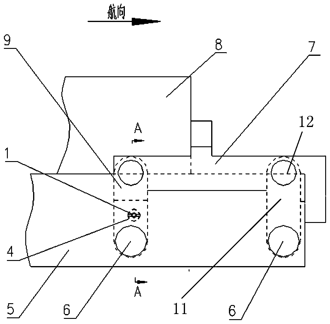
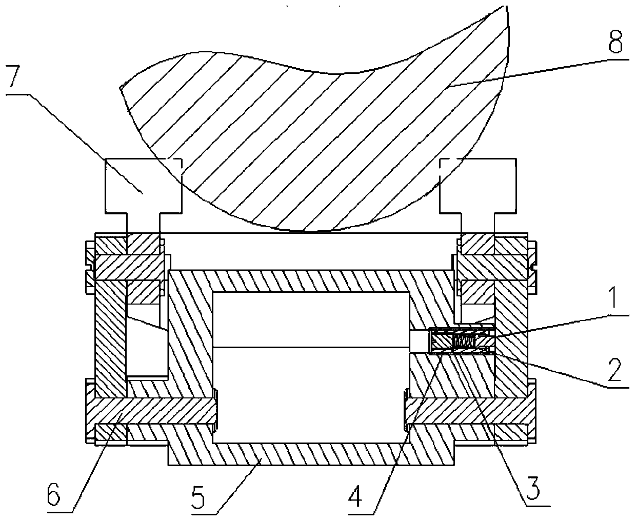
[0035] The invention provides an anti-rebound device suitable for the bullet-fixing mechanism of the sub-munition separation device, such as figure 1 As shown, it includes a crank base 5, an anti-rebound assembly and a four-bar linkage; the four-bar linkage is provided with a translation connecting rod 7, a left crank 9, a right crank 11 and two fixed rotating shafts 6; the left crank 9. One end of the right crank 11 is respectively installed on the crank base 5 through two fixed rotating shafts 6, and ...


PUM


Abstract

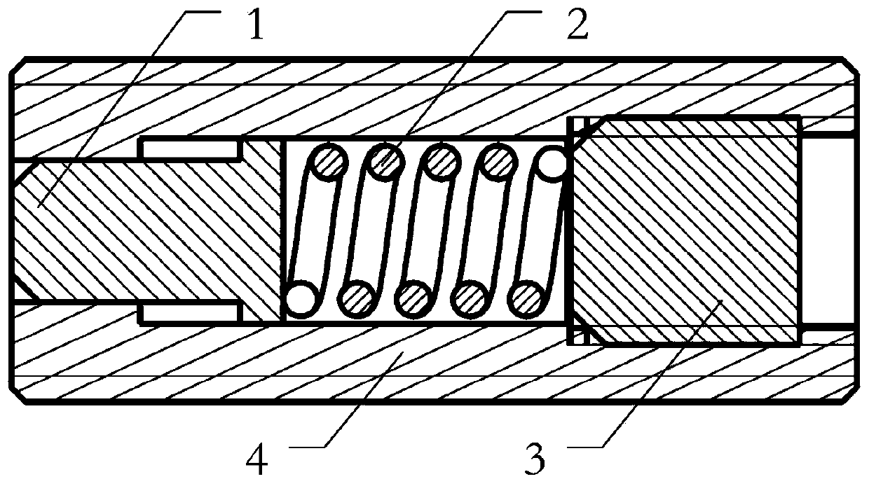
The invention provides an anti-rebound device suitable for a bomb fixing mechanism of a cluster bomb separating device. The anti-rebound device comprises a crank seat, an anti-rebound assembly and a four-connecting-rod mechanism, the crank seat is provided with a first accommodating space, the anti-rebound assembly is installed in the first accommodating space, the anti-rebound assembly is provided with a stop pin, and when a missile is launched, the four-connecting-rod mechanism rotates around a fixed rotating shaft from an initial position to achieve missile unlocking and expose the shieldedanti-rebound assembly, and the stop pin is ejected out of the anti-rebound assembly and extends to the outer portion of the crank base so as to limit the four-connecting-rod mechanism to return to the initial position. According to the anti-rebound device suitable for the bomb fixing mechanism of the cluster bomb separating device, the anti-rebound assembly is installed on the crank base, the stop pin can be automatically ejected out by combining the spring, the problem that in the prior art, a tension spring or a rubber pad cannot completely restrain rebound of the bomb fixing mechanism, andconsequently the missile is unsafe is solved, rigid anti-rebound blocking is achieved through rebound of the four-connecting-rod mechanism, and the anti-rebound device is simple in structure, safe and reliable.

Description

technical field [0001] The invention relates to the field of anti-bounce technology in weapon systems, in particular to an anti-bounce device suitable for a bullet fixing mechanism of a submunition separation device. Background technique [0002] During the storage, transportation and launching process of the missile, the missile is fixed, unlocked and separated through the connecting rod fixing mechanism. When the missile is launched, the connecting rod elastic fixing mechanism is moved to the right and downward along the axis of the rotating shaft, the elastic fixing mechanism is unlocked, and the missile is separated from the axial restraint of the connecting rod to realize separation. In order to prevent the connecting rod from bouncing back and interfering with the movement of the missile after the elastic mechanism is separated, tension springs are often used for anti-rebound or rubber cushions for cushioning when the launch impact is small. Adopt extension spring or ...

Claims


Application Information

Patent Timeline
Patent Type & Authority Applications(China)
IPC IPC(8): F41A17/00F41F1/00
CPCF41A17/00F41F1/00
Inventor 李微微张保刚俞刘建夏津刘广许斌曾清香李欣益张宏程王波兰
Owner SHANGHAI INST OF ELECTROMECHANICAL ENG
Why Eureka
Try Eureka