Rapid positioning tool for annular shell
A technology for positioning tooling and ring shells, which is applied in the field of processing tooling, can solve problems such as the rapid positioning of ring shells that are not applicable, and achieve the effects of improving fixing efficiency, fast positioning, and reliable fixing
- Summary
- Abstract
- Description
- Claims
- Application Information
AI Technical Summary
Problems solved by technology
Method used
Image

Examples
Embodiment 1
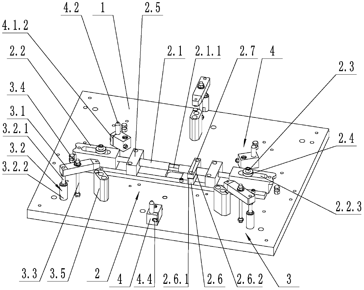
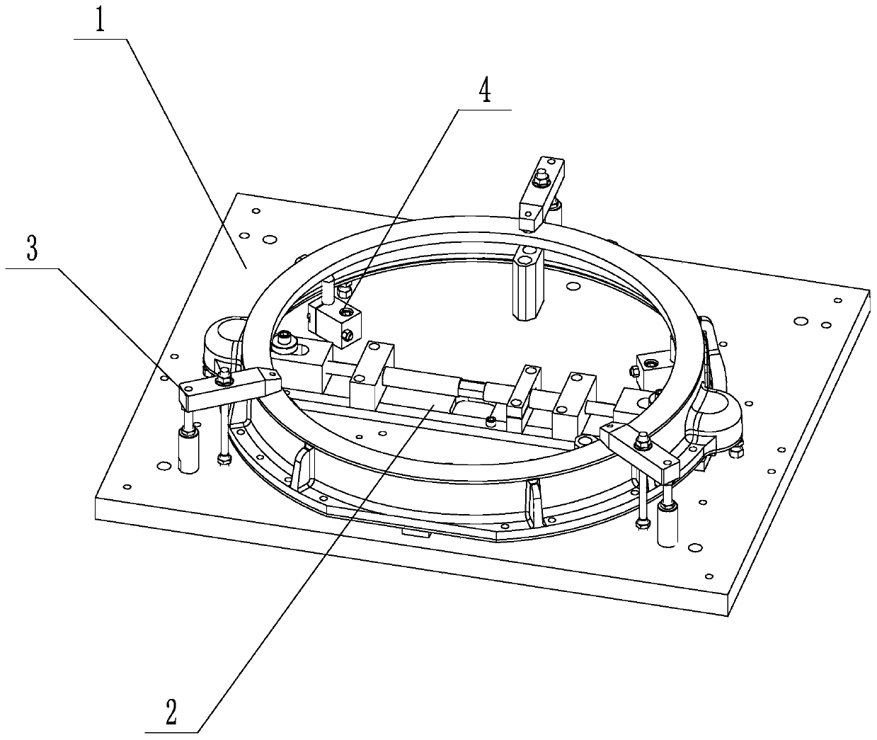
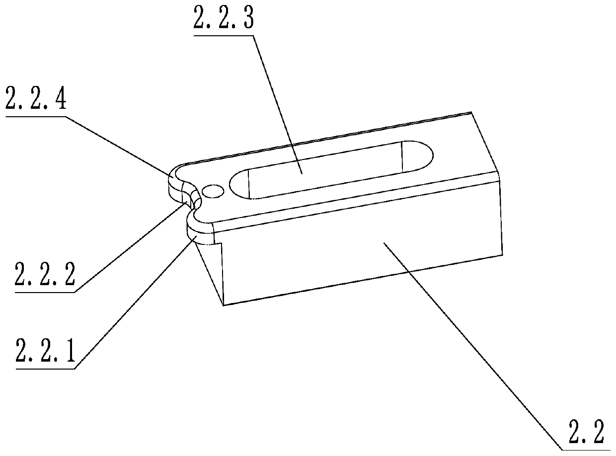
[0036] Such as figure 1 and figure 2 As shown, a rapid positioning tool for a ring shell includes a bottom plate 1 and a positioning mechanism 2. The positioning mechanism 2 includes a connecting rod 2.1, two positioning blocks 2.2, a positioning column 2.3, a fixing block 2.5, a locking block 2.6 and a locking bolt 2.7, the fixed block 2.5 is provided with a round hole, the connecting rod 2.1 is adapted to the round hole, the connecting rod 2.1 is rotationally connected with the bottom plate 1 through the fixed block 2.5, the connecting rod 2.1 is provided with a tightening structure 2.1.1, and the locking block 2.6 There are interconnected opening grooves 2.6.1 and locking holes 2.6.2, the locking holes 2.6.2 are adapted to the connecting rod 2.1, the connecting rod 2.1 passes through the locking hole 2.6.2, and one end of the locking bolt 2.7 passes through Through one side wall of the opening groove 2.6.1 and screwed with the other side wall of the opening groove 2.6.1;...
Embodiment 2
[0039] Such as figure 1 and figure 2 As shown, on the basis of Embodiment 1, it also includes 3 fixing mechanisms 3, and the 3 fixing mechanisms 3 are evenly distributed along the circumferential direction of the positioning mechanism 2; Tighten the nut 3.4 and the support block 3.5, the lower end of the adjustment column 3.2 is fixed to the bottom plate 1, one end of the pressure block 3.1 is in contact with the upper surface of the work support column 4.2, the connecting column 3.3 is arranged between the adjustment column 3.2 and the workpiece, the compression nut 3.4 and The connecting column 3.3 is threaded, and the compression nut 3.4 is arranged above the compression block 3.1 and compresses the compression block 3.1. The supporting blocks 3.5 correspond to the pressing blocks 3.1 one by one, and the supporting blocks 3.5 are arranged below the corresponding pressing blocks 3.1. The adjusting column 3.2 includes an upper column body 3.2.1 and a lower column body 3.2...
Embodiment 3
[0042] Such as figure 1 and figure 2 As shown, on the basis of Embodiment 2, an auxiliary support structure 4 is also included. The auxiliary support structure 4 includes a clamp block 4.1, a support column 4.2, a telescopic spring 4.3, and a locking member 4.4. The clamp block 4.1 is fixed to the bottom plate 1, and the clamp block 4.1 is provided with a sliding hole 4.1.1, the telescopic spring 4.3 is set in the sliding hole 4.1.1, one end of the telescopic spring 4.3 is connected with the bottom plate 1, the other end of the telescopic spring 4.3 is connected with the support column 4.2, and one end of the support column 4.2 is set on the In the installation groove, and the supporting column 4.2 is slidingly connected with the sliding hole 4.1.1, the other end of the supporting column 4.2 is set outside the clamping block 4.1, and the clamping block 4.1 and the locking member 4.4 lock the supporting column 4.2.
[0043] In the above technical solution, the auxiliary supp...
PUM
 Abstract
Description
Claims
Application Information
 - R&D
- Intellectual Property
- Life Sciences
- Materials
- Tech Scout
- Unparalleled Data Quality
- Higher Quality Content
- 60% Fewer Hallucinations
Browse by: Latest US Patents, China's latest patents, Technical Efficacy Thesaurus, Application Domain, Technology Topic, Popular Technical Reports.
© 2025 PatSnap. All rights reserved.Legal|Privacy policy|Modern Slavery Act Transparency Statement|Sitemap|About US| Contact US: help@patsnap.com