A method and device for wake-up from power
A power and wake-up source technology, applied in the field of power wake-up methods and devices, can solve problems such as complexity and uneconomical design
- Summary
- Abstract
- Description
- Claims
- Application Information
AI Technical Summary
Problems solved by technology
Method used
Image
Examples
Embodiment 1
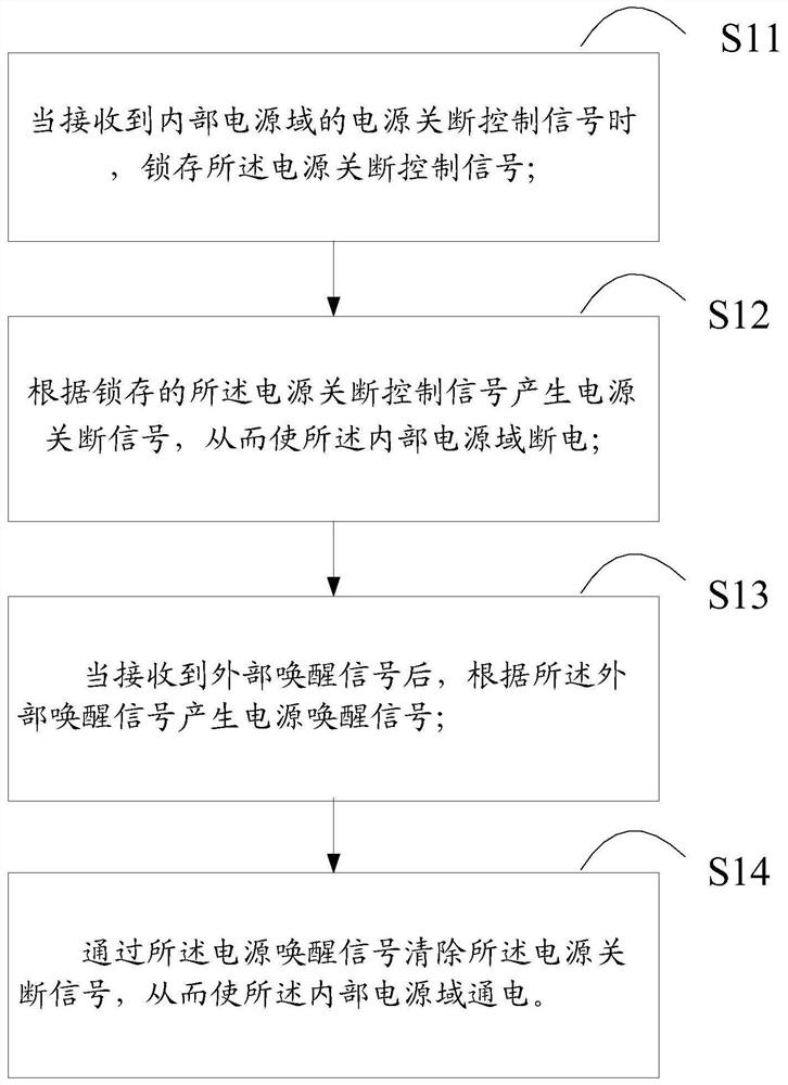
[0054] figure 1 A schematic diagram of a power wake-up method according to an embodiment of the present invention, such as figure 1 As shown, the power wake-up method in this embodiment includes:
[0055] S11. When receiving the power-off control signal of the internal power domain, latch the power-off control signal.
[0056] In an exemplary embodiment, after the power wake-up signal is generated, the power wake-up signal may be cleared by the power-off signal.
[0057] In an exemplary embodiment, the power-off control signal may be latched by the first latch.
[0058] S12. Generate a power-off signal according to the latched power-off control signal, so as to power off the internal power domain.
[0059] In an exemplary embodiment, the power-off signal output by the first latch may be delayed by a delay circuit.
[0060] S13. After receiving the external wake-up signal, generate a power wake-up signal according to the external wake-up signal.
[0061] In an exemplary em...
Embodiment 2
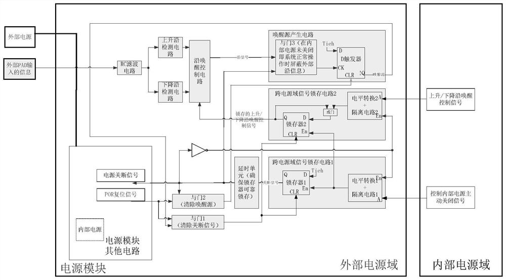
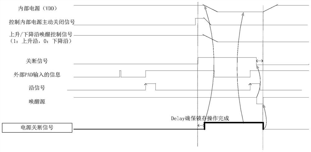
[0069] figure 2 It is a schematic diagram of a power wake-up circuit according to the second embodiment of the present invention. image 3 This is a waveform diagram of the power wake-up circuit according to the second embodiment of the present invention. like figure 2 As shown, it includes a cross-power domain signal latch circuit 1, a cross-power domain signal latch circuit 2, a wake-up source generation circuit, an edge wake-up control circuit, a rising edge detection circuit, a falling edge detection circuit, RC filter circuit, AND gate 1, AND gate 2, delay unit, etc.
[0070] Wherein, the cross-power domain signal latch circuit 1 may include an isolation circuit 1 , a level conversion 1 , and a latch 1 .
[0071] Control of the internal power domain The active shutdown signal of the internal power supply (ie, the power supply shutdown control signal above) is input to the isolation circuit 1 of the signal latch circuit 1 across the power domain, and after level conve...
Embodiment 3
[0087] Figure 5 It is a schematic diagram of the power wake-up device according to the third embodiment of the present invention, such as Figure 5 As shown, the power wake-up device of the third embodiment includes:
[0088] The power-off signal generating module is configured to latch the power-off control signal when receiving the power-off control signal of the internal power domain; and generate the power-off signal according to the latched power-off control signal, thereby powering down the internal power domain;
[0089] a power wake-up signal generating module, configured to generate a power wake-up signal according to the external wake-up signal after receiving the external wake-up signal;
[0090] The module for clearing the power off signal is used for clearing the power off signal through the power wake-up signal, so that the internal power domain is powered on.
[0091] In an exemplary embodiment, the power-off signal generating module includes a first latch f...
PUM
 Abstract
Description
Claims
Application Information
 - R&D
- Intellectual Property
- Life Sciences
- Materials
- Tech Scout
- Unparalleled Data Quality
- Higher Quality Content
- 60% Fewer Hallucinations
Browse by: Latest US Patents, China's latest patents, Technical Efficacy Thesaurus, Application Domain, Technology Topic, Popular Technical Reports.
© 2025 PatSnap. All rights reserved.Legal|Privacy policy|Modern Slavery Act Transparency Statement|Sitemap|About US| Contact US: help@patsnap.com


