
Near space glider state estimation method, storage medium and computing device

A near-space and state estimation technology, applied in design optimization/simulation, etc., can solve problems such as large errors

Pending Publication Date: 2020-07-17
BEIJING INST OF ELECTRONICS SYST ENG
View PDF2 Cites 0 Cited by
  • Summary
  • Abstract
  • Description
  • Claims
  • Application Information

AI Technical Summary

Problems solved by technology

However, the state estimation value obtained by using the Singer model is used for subsequent ballistic prediction, and the error is large

Method used


Image

  • Near space glider state estimation method, storage medium and computing device
  • Near space glider state estimation method, storage medium and computing device
  • Near space glider state estimation method, storage medium and computing device

Examples


Embodiment Construction

[0097] In order to make the technical solutions and advantages of the present invention clearer, the implementation manners of the present invention will be further described in detail below in conjunction with the accompanying drawings.

[0098] Definition of coordinate system

[0099] In order to obtain the state estimation of the hypersonic glide body in the near space, it is necessary to establish a motion model to describe the motion of the hypersonic glide body in the near space. For this, several related coordinate systems need to be defined first.

[0100] 1. Observe the inertial coordinate system

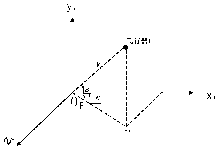
[0101] The origin is the point O where the ground radar is located F , O F y-axis plumb up, O F The x-axis is in the target incoming plane, perpendicular to O F y-axis, pointing to the target is positive, O F The z-axis is determined by the right-hand rule. This coordinate system is fixed in the inertial space at the instant of launch of the glider.

[0102] 2. Balli...


PUM


Abstract

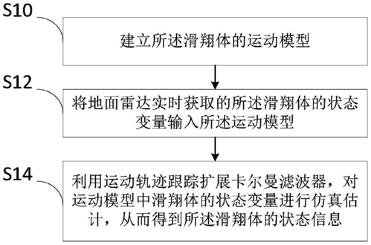
The invention discloses a near space hypersonic gliding body state estimation method. The method comprises the following steps: S10, establishing a motion model of a gliding body; S12, inputting the state variable of the gliding body, which is acquired by a ground radar in real time, into the motion model; S14, tracking an extended Kalman filter by utilizing a motion trail; performing simulation estimation on the state variables of the gliding body in the motion model, so that the state information of the gliding body is obtained. In the invention, a new maneuvering model of the near-space hypersonic gliding body is provided, wherein by means of the extended Kalman filtering, the state estimation method for the gliding body is provided.

Description

technical field [0001] The present invention relates to a method for estimating the state of a near-space gliding body, and more particularly, to a method for estimating the state of a near-space hypersonic gliding body, a storage medium, and a computing device. Background technique [0002] Hypersonic glide warhead in near space is an offensive missile that can glide unpowered for thousands to more than 10,000 kilometers in near space. The booster of the missile is three-stage, boosted to a predetermined height, the hypersonic glide body (HGB) is separated from the booster, and continues to attack the predetermined target at a distance of several thousand kilometers. The attack speed in the final stage may reach Mach 4. Point strike accuracy within 10m. This type of aircraft adopts the more common "cone + skirt + cross wing" layout, and has strong long-range gliding and maneuvering flight capabilities in adjacent spaces. [0003] As disclosed in Patent Publication No. CN ...

Claims


Application Information

Patent Timeline
IPC IPC(8): G06F30/20
Inventor 李君龙周荻曹颖陈晓波秦雷邓洪哲
Owner BEIJING INST OF ELECTRONICS SYST ENG
Learn More